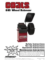
background image

ii •

Important: Always read and follow the instructions.

NOTICE

Read entire manual before assembling,
installing, operating, or servicing this
equipment.

Summary of Contents for Coats 885

Page 1: ...ons READ these instructions before placing unit in service KEEP these and other materials delivered with the unit in a binder near the machine for ease of reference by supervisors and operators 1601 J P Hennessy Drive La Vergne TN USA 37086 615 641 7533 800 688 6359 www coatsgarage com HENNESSY INDUSTRIES LLC Manufacturer of COATS AMMCO and BADA Automotive Service Equipment and Tools ...

Page 2: ...ii Important Always read and follow the instructions NOTICE Read entire manual before assembling installing operating or servicing this equipment ...

Page 3: ...ts ALU 10 Wheel Dimensions Setting 10 Result of the measurement and weight application 11 Balancing With A Mix Of Adhesive and Clip On Weights and Static Balancing 12 Static Unbalance 13 Exact Positioning of the Adhesive Weight By Means Of The Gauge With Clips 13 Hide The Adhesive Weights Behind Spoke 14 Automatic Minimization Of Static Unbalance 14 Unbalance Match Mount Balance 15 Setup 16 Menu A...

Page 4: ... overheat Care should be taken to arrange the cord so that it will not be tripped over or pulled 8 Keep guards and safety features in place and in working order 9 Wear proper clothing Safety toe non slip footwear and protective hair covering to contain hair is recommended Do not wear jewelry loose clothing neckties or gloves when operating the balancer 10 Keep work area clean and well lighted Clut...

Page 5: ...perating practices Always wear durable work clothing during tire service activity Loose fitting clothing should be avoided Tight fitting leather gloves are recommended to protect operator s hands when handling worn tires and wheels Sturdy leather work shoes with steel toes and oil resistant soles should be used by tire service personnel to help prevent injury in typical shop activities Eye protect...

Page 6: ... all the dangers warnings and cautions in this manual For additional copies of either or further information con tact Hennessy Industries Inc 1601 J P Hennessy Drive LaVergne TN 37086 3565 615 641 7533 or 800 688 6359 www coatsgarage com Standard Safety Devices Stop push button for stopping the wheel under emergency conditions A hood guard of high impact plastic that is designed to prevent the cou...

Page 7: ... enter Width value 6 Lower the hood press Start wheel spins and unbalances are measured and displayed The corrective weight amount appears in the digital readout windows 7 Raise hood after tire stops rotat ing Note Wait for wheel to stop before raising the hood 8 Rotate wheel to inboard left plane position of unbalance 9 Attach inboard left plane corrective weight Attach specified weight amount at...

Page 8: ...tained only when all persons using the unit are fully trained in its parts and operation Each user should learn the function and location of all controls Prevent accidents and injuries by ensuring the unit is properly installed operated and maintained Control Panel or Video Display Panel Plug back of machine ON OFF Weight Tray with Pockets for Corrective Weights Offset Arm Measures A D of Tire Whe...

Page 9: ...t Figure 3 shows an example of each weight Corrective Weight Examples For Best Results use BADA Brand Wheel Weights Power Switch The ON OFF switch is located on the back of the balancer Important Always read and follow the instructions 3 Clip on Weight Tape A Weight ON OFF Power Switch ...

Page 10: ...using personal injury and property damage Standard Back Cone Collet Mounting Most original equipment and steel wheels can be mounted properly using this method The wheel is cen tered on a cone from the inner side of the hub 1 Select the cone collet that best fits the center hole in the wheel Slide the cone collet onto the shaft with the large end towards the cone spring 2 Lift wheel onto the shaft...

Page 11: ...The wheel must be forced firmly against the faceplate Note Do not front cone chrome or clad wheels Front Cone Collet Mounting Cone Collet Shaft Faceplate Hub Nut with Pressure Cup Spacer Alternate Mounting If the wheel has a protruding outer hub which will not permit the use of the pressure cup or the cup will not permit the hub nut to engage at least four turns of the shaft this alternate method ...

Page 12: ...sh button FUNCTIONS MENU Push button menu selection confirmation Push button cycle start Push button emergency home Push button position repeater Push button SPLIT hidden weight Minimum Maximum Menu Button Push button g oz measuring unit selection Default is OFF see pg16 to turn ON this feature 2 3 9 11 1 6 7 10 8 12 4 14 13 5 Digital readouts AMOUNT OF UNBALANCE inside outside static Push button ...

Page 13: ... the rim as shown in the figure 2 While the gauge is moving the following appears 3 Hold the gauge in position for at least 2 seconds MENU ACOUSTIC SIGNAL the acquisition of the dimensions is accompanied If the acoustic signal is enabled by a beep Measurement stored 4 Set the distance and diameter gauge to the home position The balancing machine automatically interprets the presence of a rim with ...

Page 14: ...8 Important Always read and follow the instructions Page left intentionally blank ...

Page 15: ...e symbol is shown on the Display Item 3 4 on Pg 6 on the side corresponding to the active correction plane 3 Manually apply the number of weights shown on the display on the rim at 12 o clock using clip on weights If the out of balance is less than the chosen threshold value appears instead of the out of balance value to indicate on that particular side that the wheel is in tolerance If AUTOADAPTI...

Page 16: ...ccompanied If the acoustic signal is enabled by a beep Set the gauge to the home position The balancer automatically interprets the presence of a rim with adhesive weight correction If the wheel dimensions have been entered incorrectly the parameters can be modified without repeating the balancing spin 1 Press 2 Set the value of the dimensions in sequence dI inside weight distance dE outside weigh...

Page 17: ... reached 2 The symbol is shown on the Display Item 3 4 on Pg 6 on the side corresponding to the active correction plane 3 Manually apply on the rim at 12 o clock the amount of weight shown on the display by using adhesive weights If the out of balance is less than the chosen threshold value appears instead of the out of balance value to indicate on that particular side that the wheel is in toleran...

Page 18: ...ock Clip on weight at 12 o clock Adhesive weight at 12 o clock Adhesive weight at 12 o clock STATIC Adhesive weight at 12 o clock After dimension acquisition in ALU mode pressing the 3 1 2 buttons you can select one of the following correction modes The adhesive weight application distance and diameter are measured by means of the automatic gauge except for the static unbalance where the dimension...

Page 19: ...ive weights on the inside of the rim Fit the correction weight in the specific gauge seat with the adhesive part facing upwards Bring the wheel into correct angular position for the plane to be corrected If the wheel clamp option is enabled MENU the wheel is automatically clamped in the correction position Pull out the gauge until the leds Item 5 on Pg 6 light up next to the correction weight MENU...

Page 20: ...s AUTOMATIC MINIMIZATION OF STATIC UNBALANCE This program is designed to improve the quality of balancing without any mental effort or loss of time by the operator In fact by using the normal commercially available weights with pitch of 5 in every 5 g and by applying the two counterweights which a conventional wheel balancer rounds to the nearest value there could be a residual static unbalance of...

Page 21: ... a Close the guard and press the button spin 2 Make a reference mark on the flange and the rim using a piece of chalk for example With the aid of a tire remover turn the tire on the rim by 180 Refit the wheel in such a way that the reference marks on the rim and the flange coincide if start from the guard is disabled MENU to perform a Close the guard and press the button spin 3 RH display percenta...

Page 22: ...omatic RIM DISTANCE gauge Calibration of automatic DIAMETER gauge UNBALANCE OPTIMISATION WHEEL DIMENSIONS SETTING g oz button on the panel ON OFF if foreseen screen saver operating time in minutes wheel locking ON OFF if foreseen adhesive weight width tolerance on the correction planes start from guard closing ON OFF approximates 1 5g 0 1 0 25oz beep signal ON OFF unbalance unit of measure g oz De...

Page 23: ...al Service BALANCING MACHINE CALIBRATION Calibrate in OZ mode To calibrate the balancing machine use a wheel with steel rim of average dimensions e g 16 To properly perform the procedure Mount a wheel on the machine even unbalanced and very carefully set its dimensions Setting incorrect measurements will result in the machine not being correctly calibrated and balancing of subsequent wheels will h...

Page 24: ...ight is at the top 12 o clock and press 5 Pull A D Arm to the Rim Flange rotate wheel to center Cal weight to the A D weight clip and press Pressing the button a default value is set CALIBRATION COMPLETE To cancel calibration at any time press AUTOMATIC GAUGES CALIBRATION Distance gauge calibration 1 Display the distance gauge CALIBRATION function from the SETUP menu 2 Leave the distance gauge in ...

Page 25: ...he Home position and repeat the calibration operation exactly as described above If the error persists contact the Technical Service Department In the event of incorrect input in the rim distance gauge calibration function press to cancel it Diameter gauge calibration E 1 Display the diameter gauge CALIBRATION function from the SETUP menu 2 Place the gauge rod on the spindle shell as shown in the ...

Page 26: ... back into HOME position and repeat the calibration operation as described above if the error persists contact Technical Service If erroneously accessing the diameter gauge calibration function press to cancel it ADHESIVE WEIGHT WIDTH Indicates the average width of the adhesive weights on the market Change ONLY if the width of the adhesive weights used for unbalance correction differ 3 mm with res...

Page 27: ...normal operator ERROR PROBLEM POSSIBLE SOLUTIONS Black The wheel balancer does not switch on Err 1 No rotation signal Err 2 Speed too low during detection During the unbalance measurement revo lutions the wheel speed has fallen to below 42 rpm Err 3 Unbalance too high Err 4 Rotation in opposite direction After pressing START the wheel starts turning in the opposite direction anticlockwise Err 5 Gu...

Page 28: ... 100 g and verify he response of the machine Replace the computer board Use the self diagnostics function to check the encoder Check the connections on the power board Replace the computer board Use the self diagnostics function to check the encoder Check the connections on the power board Replace the computer board The minimum distance between the spokes where the unbalance is to be split must be...

Page 29: ...rrier promptly Support your claim with copies of the bill of lading freight bill invoice and photographs if possible Although COATS responsibility ceases upon delivery of the shipment to the carrier we will gladly assist in tracing lost shipments Our willingness to assist in every possible manner does not make COATS respon sible for collection of claims or replacement of lost or damaged materials ...

Page 30: ...t function properly and may produce inaccurate balance readings Do not operate the balancer while it is on the pallet Select a location for the balancer that provides a level solid floor and adequate clearance around and above the balancer Make sure the location selected has enough room above and behind the unit so the hood can be raised completely The location must also pro vide working room for ...

Page 31: ...lace it in its operating location Hood Installation 5 Remove one screw holding the Hood bracket to the balancer arm 6 Align the Hood bracket with the balancer arm and secure with three screws Connect to Power Your factory trained COATS Service Technician should do the final check to verify the power installation before connecting the balancer to a power supply Failure due to improper power connect...

Page 32: ...85611582 00 05 19 Copyright 2019 Hennessy Industries and COATS All Rights Reserved Printed in USA NOTES ...

Reviews: