COATS 1000/1000D Wheel Balancer • 7
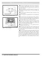
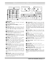
Control Panel
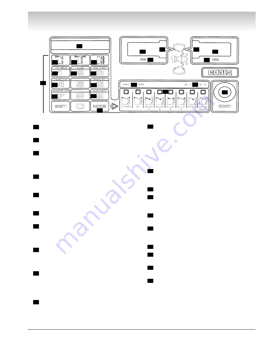
Keypad -
User enters information and selects
function using these keys.
Wheel Measurement Display -
Displays A, W,
and D values.
Wheel Offset (A) -
The distance between the
inner rim flange and the edge of the balancer. Refer to
Data Entry beginning on page 9 for detailed instruc-
tions.
Wheel Width (W) -
The width of the rim between
the inner and outer rim flanges. Refer to Data Entry
beginning on page 9 for detailed instructions.
Wheel Diameter (D) -
The diameter of the wheel
at the weight location. Refer to Data Entry beginning
on page 9 for detailed instructions.
Calibrate -
Places the balancer in the Calibrate
Mode. Press and hold the SHIFT key, and press 1.
Clear -
Clears all entered measurements and user
preferences for the operator memory in use (Operator
A/B). The other operator memory remains intact.
Press and hold the SHIFT key, and press 2.
Hood Start -
Sets the balancer to automatically
start the spin cycle when the hood is lowered. Press
and hold the SHIFT key, and press 3. Repeat the key
sequence to turn the option off.
Blank Rim -
Turns the wheel diameter measure-
ment display off (balancer continues to utilize this
measurement). Press and hold the SHIFT key, and
press 4. Repeat the key sequence to turn the display
back on.
Round Off -
Toggles the balancer between the
high accuracy mode (0.01-ounce increments) and the
normal mode (0.25-ounce increments). Press and hold
the SHIFT key, and press 6.
Operator A/B -
Toggles the balancer between
two operator memories. Allows the balancer to be
used by a second operator without clearing the meas-
urements or data stored by the first operator. All
measurements and preferences entered into one
operator memory are retained when the other opera-
tor memory is selected. Press and hold the SHIFT key,
and press 7.
Ounce/Gram -
Toggles the balancer between
ounces or grams. Press and hold the SHIFT key, and
press 9.
Mode -
Selects the desired balancing mode.
Balancing Modes -
Press the MODE key to
select from the 8 available modes. The LED above the
mode will illuminate to indicate the mode is selected.
Weight Unit LEDs -
Indicates that weight read-
ings are shown in ounces or grams (see 12).
Operator LEDs -
Indicates operator memory in
use (see 11).
Start Button -
Press to start a spin cycle.
Weight Displays -
Indicate the weight amount to
be attached to the wheel.
Weight Position LEDs -
Center LEDs flash when
correct weight position is at top-dead-center.
Rim/Tire Reading Indicators -
When lit, the
readings in the displays represent the weight values
for the rim and tire individually. Used only with Match-
Mount.
20
19
18
17
16
15
14
13
12
11
10
9
8
7
6
5
4
3
2
1
Direct Drive
18
1
2
3
4
5
6
7
8
9
10
11
12
13
14
15
16
17
18
19
19
20
20


