8
WaTer sofTener draininG ProCedure
In cold weather climates it is common for plumbing systems that
are not in use to be “winterized“ or drained of all water to prevent
any damage that may be caused by the excessive expansion of
water when it freezes. To prevent damage to a water softener it
must be properly drained also. A simple way to properly drain
or winterize a water softener is to use compressed air to force
all of the water out of the softener mineral tank. The following
procedure will explain the process:
1) Initiate the softener into a manual regeneration cycle. After
the refill cycle, advance control to backwash by pressing the
NEXT button until backwash appears on the screen. Allow
it to complete the backwash cycle (this will clean the media)
and start into the brine-draw cycle. Allow the regeneration
to continue in the brine draw cycle until the brine is drawn
out of the brine tank and the air check at the bottom of the
brine pick-up tube shuts off. NOTE: Be sure you have salt
in the brine tank and allow 1 hour minimum to make a
saturated brine. It is important that any liquid left in the
softener tank when you finished blowing out system be
saturated brine solution to prevent any damage to the
softener. At this time no more brine is introduced into the
softener and the slow rinse process begins.
2) Turn the water supply inlet and outlet valves off to the water
softener as soon as the air check shuts off and no more brine
is being drawn into the softener (at the beginning of the slow
rinse process).
3) Unplug the electric power leaving the softener control valve
in the brine draw cycle.
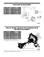
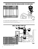
4) Remove the brine refill elbow assembly from the control
valve. Remove the refill flow control retainer assembly from
the elbow. Reinstall the elbow assembly and secure with
the locking clip. Disconnect the brine tube at the top of the
brine tank and force air into the brine tube toward the softener
mineral tank and control valve. The air will force the brine/
water solution that was drawn into the mineral tank out to
drain through the control valve drain line. (An air compressor
blow gun attachment with a portable air compressor works
well.) Reinstall the brine line flow control retainer in side
of the refill elbow assembly. Reinstall the brine refill elbow
assembly and secure with locking clip.
CAUTION: You do not want to apply any more pressure than
necessary to force the brine/water out of the mineral tank.
The small amount of brine/water that may be left in the
mineral tank will not expand enough to cause any damage
to the softener when it freezes.
If your softener is equipped with an optional bottom drain
on the mineral tank, you will have to follow all of the same
procedures with the exception of the need for compressed air.
With the brine tube disconnected from the brine tank, raise
it to a level above the softener control valve and temporarily
secure it in this position. Now open the drain valve at the
bottom of the mineral tank and allow all brine/water to drain
from the mineral tank.
CAUTION: If a hose is connected to the drain valve to direct
the brine/water to a floor drain be sure it runs downward and
is unobstructed. When brine/water quits running at the drain,
be sure to leave the drain valve open until you start the system
up again.
5) At this time the brine tank has very little water left in it. What
liquid is left in the brine tank is saturated brine, provided
that there is still salt left in the tank. Saturated brine will not
freeze solid and cause any damage and does not have to
be drained any further from the brine tank.
If there is no salt left in the brine tank when the system is
drained we recommend dumping all of the water out of the
brine tank at this time. See brine tank cleaning instructions.
(#2 in Maintenance section, page 7)
6) CAUTION: It is important at this time to be assured that the
inlet/outlet water supply piping is properly drained. Depend-
ing on how the water supply piping was routed to the water
softener control valve, a water loop or trap may have been
created.
Sometimes drain valve(s) are installed at the bottom of the
loop to assure all water can be drained out. If not it may be
necessary to disconnect the control valve from the piping
system and open the inlet/outlet valve(s) to allow all the water
to drain from the piping. This should be done after the rest
of the plumbing system is drained.
7) Draining or winterizing of your softener is complete. Refer
to the start-up procedures on page 6 when you are ready to
start your softener.
WaTer sofTener disinfeCTion
The construction materials of your water softener will not support
bacterial growth nor will these materials contaminate a water
supply. However, the normal conditions existing during shipping,
storage, and installation indicate the advisability of disinfecting
a softener after installation, before the softener is used to treat
potable water. In addition, during normal use a softener may
become fouled with organic matter or in some cases, with bac-
teria from the water supply.
Therefore, every water softener should be disinfected after
installation, some will require periodic disinfection during their
normal life. Disinfect as follows:
SODIUM HYPOCHLORITE (household bleach)
5.25% SODIUM HYPOCHLORITE solutions are available
under such trade names such as Clorox, Linco, Bo Peep,
White Sail and Eagle Brand Bleach. If stronger solutions are
used, such as those sold for commercial laundries, adjust
the dosage accordingly.
1. Dosage:
a. Softening resin; 1.2 fluid ounce per cubic foot of
resin.
2. Add the required amount of hypochlorite solution to the
brine well of the brine tank.
a. Proceed with the normal regeneration. Press REGEN
and allow the water softener to go through a normal
regeneration.


