8
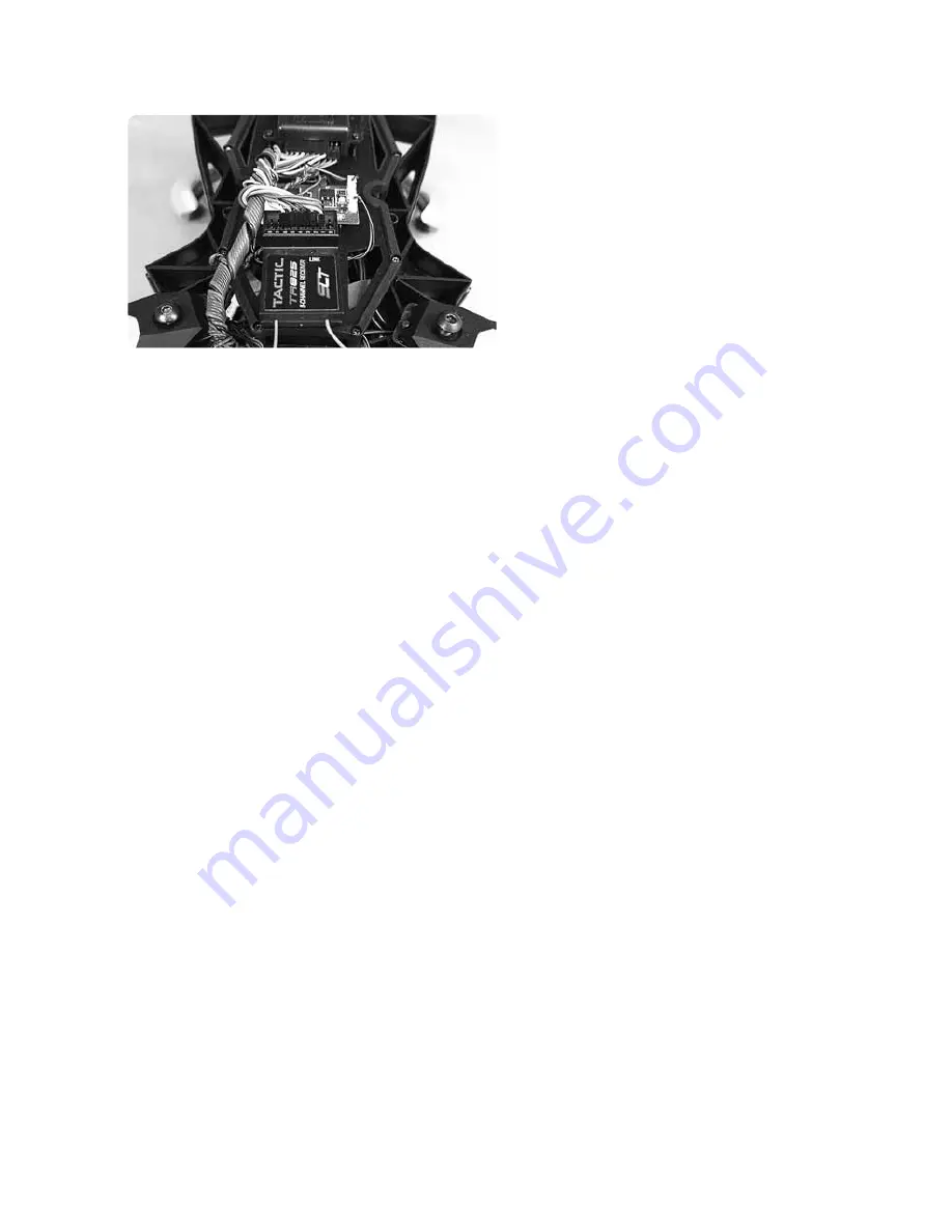
Linking the transmitter and receiver
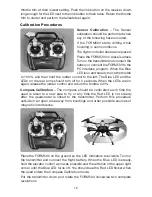
Remove the props and the canopy.
Turn on the transmitter.
Set the Ch. 5 and Ch. 6 switches
to the center positions for Position
Hold & Altitude Hold mode.
Center the controls for Channel
7 & 8.
Lower the throttle trim to the
lowest setting.
Connect the battery to the FORM500.
While holding the throttle at 0%, press and hold the link button on the receiver
until the Red LED on the receiver flashes twice. The FORM500 will beep once
when the flight controller first receives a signal from the transmitter and the
Blue LED indicator on the FORM500 will turn on.
Return the throttle trim to
the center position when the receiver is linked.
PC Interface
The PC Interface displays current data from the FORM500 flight controller and
allows some features to be customized. The program needs to be installed on
a Windows PC along with the driver for the USB cable. After the program is
installed, right-click on it and select properties. Click on the compatibility tab.
Click on the box next the “Run this program as an administrator”.
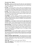
ComPort
This window is used to select the communications port assigned to the USB
cable. After the communications port has been selected (normally not Com1),
click on the Connect Button. The FORM500 is connected to the PC Interface
when the Connect Button changes to the Disconnect and there is live data in
the Sensor Data window.
Flying Status
This window shows the current function(s) that have been selected with the
Ch.5 and Ch.6 switches.
The GPS Mode Status window displays the current function selected by the
CH. 5 switch. This switch controls the Altitude Hold mode (manual control),
Position Hold and Return to Home functions. The Alt Smart Status window
displays current function selected by the CH. 6 switch. The FORM500 is always
in the Altitude Hold mode. The CH. 6 switch is used to turn the Headless Flight
function on or off.
Summary of Contents for FORM500
Page 17: ...17 ...
Page 20: ... HMXE0863 ...


