


11
Press and hold the Firmware Button next to the I/O port on the FORM500 and
connect the USB cable. The alarm will beep and the three status LEDs at the
back of the FORM500 will flash. The status of the update will be displayed in
the horizontal gauge and in the black window. Release the button when the
update process has started. The alarm will stop the continuous tone and beep
once when the update is finished. The firmware update should not change any
of the adjustable parameters in the Flight Controller.
Failsafe Test
This test should be performed any time the receiver or transmitter has been
changed so they need to be re-linked using the procedure in the previous
section. To check the failsafe:
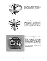
Remove the props and canopy.
Link the transmitter and the FORM500. Ch. 5 and Ch. 6 switches should be in
the away position.
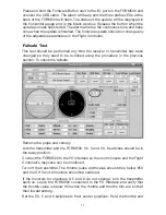
Connect the FORM500 to the PC Interface so the control inputs and the Flight
Controller’s response can be monitored.
Turn off the transmitter. The throttle pulse width value should drop below 950
and the CH 5 and 6 monitors should be centered.
If the monitors for channels 3, 5 and 6 do not change, turn the transmitter
back on. Leave the FORM500 connected to the PC Interface and verify that
the throttle value is below 950 when the throttle and throttle trim are both at
their lowest setting.
Set the Ch. 5 and 6 switches to their center positions. Hold the throttle and
Summary of Contents for FORM500
Page 17: ...17 ...
Page 20: ... HMXE0863 ...