background image

7

TTX810

Batteries

The TTX810TS comes with 4 AA alkaline batteries. Rechargeable NiCd or NiMH 

batteries can also be used. There is a charge jack on the side of the transmitter 
that can be used with rechargeable batteries.

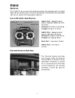
Control/Switch Identification

Switch Ch.5

 - 

Away

 (pushed 

back) is Stabilize Mode (no GPS 
functions)

Centered

 is Position Hold Mode

Forward

 is Return to Home

Switch Ch.6

 - 

Away

 (pushed 

back) is Altitude Hold Mode

Centered

 is Altitude Hold Mode

Forward

 is Headless Mode

Knob Ch.7

 - Accessory Control 

Switch Ch.8

 – Accessory 

Control

Channel Reverse Switches

The Channel reverse switches 

are located inside the battery 
compartment on the back of the 
transmitter. Channels 1-4 should 
be on (reversed) and Channels 
5 and 6 should be off (normal). 

Channels 7 and 8 are used for 

accessories.

Summary of Contents for FORM500

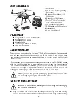
Page 1: ...urchase Heli Max products are to be used by ages 14 and over Manual Specifications and Description Changes The instruction manual warranties and other associated documentation are subject to change without notice Hobbico assumes no responsibility for inadvertent errors to this manual WARNING INSTRUCTION MANUAL SPECIFICATIONS Span 13 6 in 345mm Size 19 7 in 500 mm diagonal span 9 25 in 235mm Height...

Page 2: ...se feel free to contact us at helihotline hobbico com For the latest technical updates or manual corrections for the FORM500 please visit the Heli Max web site at www helimax rc com Open the Quadcopters link and then select the FORM500 quadcopter If there is any new technical information changes or important updates to this model a tech notice box will appear on the page Click the tech notice box ...

Page 3: ...ow any signs of wear or fatigue BATTERY WARNINGS USAGE GUIDELINES Please read and understand the following regarding the usage of LiPo batteries Through the use of the included LiPo battery you have assumed all risk and responsibility regarding a LiPo battery and its use Battery Warnings ALWAYS unplug your battery from either the charger or quadcopter after use NEVER store your quadcopter with the...

Page 4: ...d for any damage resulting from the use by the user of the final user assembled product By the act of using the user assembled product the user accepts all resulting liability If the buyer is not prepared to accept the liability associated with the use of this product the buyer is advised to return this kit immediately in new and unused condition to the place of purchase To make a warranty claim s...

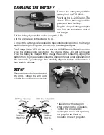
Page 5: ...pter The Charge Status LED will turn red and the 3 Cell Status LEDs will come on when the charge cycle has started The Charge Status LED will turn Green when the battery is charged If the Charge Status LED is flashing unplug the battery from the charger and consult the charger manual for an explanation of the error code Typical charge time for a fully depleted battery will be around 1 hour and 40 ...

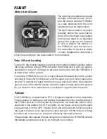
Page 6: ... is flashing arm the motors and take off Hover and make sure the quad is responding to stick inputs from both sticks If the quad is making any unusual sounds or vibrations land and investigate before continuing the flight FORM500 INDICATORS AND ALARMS LED Indicators Blue LED Steady light indicates that the controller is receiving signals from the transmitter Flashing slowly indicates that Headless...

Page 7: ... Mode no GPS functions Centered is Position Hold Mode Forward is Return to Home Switch Ch 6 Away pushed back is Altitude Hold Mode Centered is Altitude Hold Mode Forward is Headless Mode Knob Ch 7 Accessory Control Switch Ch 8 Accessory Control Channel Reverse Switches The Channel reverse switches are located inside the battery compartment on the back of the transmitter Channels 1 4 should be on r...

Page 8: ...ws PC along with the driver for the USB cable After the program is installed right click on it and select properties Click on the compatibility tab Click on the box next the Run this program as an administrator ComPort This window is used to select the communications port assigned to the USB cable After the communications port has been selected normally not Com1 click on the Connect Button The FOR...

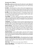
Page 9: ...s when in Position Hold or is in a Return to Home routine The factory setting for this adjustment is MED The HIGH setting could be used if the quad is heavily loaded The LOW setting is best used when FORM500 is not carrying any accessories Attitude Window This artificial horizon displays the FORM500 s attitude for both the roll and the pitch axis When on a level surface the line separating the blu...

Page 10: ...be The Green LED will come on when this value is below 6 meters and will start flashing when the value is below 3 meters Azimuth The number of degrees from North that the FORM500 is pointing Heading The number of degrees from North that the FORM500 is pointing Version The current firmware version Limit Window Dist Limit This window is used to set a distance the FORM500 can fly from the launch poin...

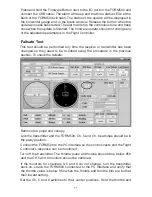
Page 11: ...s been changed so they need to be re linked using the procedure in the previous section To check the failsafe Remove the props and canopy Link the transmitter and the FORM500 Ch 5 and Ch 6 switches should be in the away position Connect the FORM500 to the PC Interface so the control inputs and the Flight Controller s response can be monitored Turn off the transmitter The throttle pulse width value...

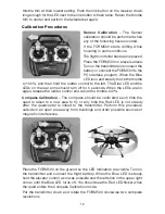
Page 12: ...lue LED and the LEDs on the rear arms should turn off for 5 seconds When the LEDs are on again release the rudder control and return the throttle to 0 Compass Calibration The compass should be calibrated each time the quad is taken to a new area to fly or any time the Red LED is not steady after the quadcopter is linked to the transmitter Perform this procedure outside in an open area away from bu...

Page 13: ... so the nose moves up and then toward you Continue to rotate the quad in the same direction for two revolutions Place the FORM500 back on the ground with the LED indicators visible Pick up the transmitter and hold the elevator control down again and put the left stick in the upper left corner until the Blue LED flashes Release the right stick and return the left stick to the 0 throttle position ...

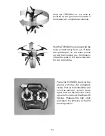
Page 14: ...ORM500 bring it to a hover at least three feet above the ground and slowly move the throttle down until the quad is an inch or two above the ground To prevent the quad from bouncing up and down when it touches the ground reduce the throttle quickly when the quad is barely above the ground As you become more experienced you will learn to gently land the quad Failsafe The FORM500 is programmed to RT...

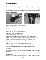
Page 15: ...C Remove 4 screws that hold the arm connector hinge to the chassis Pull the wires back through the arm connector and the inside of the arm Loosen the 4 mounting screws for the motor and remove the motor Reverse these steps to install the new motor Do not replace the upper chassis tray until the motor has been checked Put some thread locking compound on the motor screws When installing the arm conn...

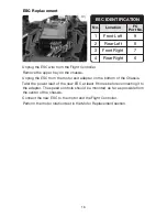
Page 16: ...ay on the chassis Unplug the ESC from the motor and adapter on the bottom of the Chassis Twist the power lead of the new ESC at least 9 times before connecting it to the adapter The speed controls should be mounted as far as possible from the center of the chassis Connect the new ESC to the motor and the Flight Controller Perform the motor rotation test in the Motor Replacement section ...

Page 17: ...17 ...

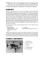
Page 18: ...ight Controler Rear LED Cable 21 HMXE2272 Flight Controller RX Cable 22 HMXE2273 Body Set w Decal Yellow 23 HMXE2274 Arm Cover Set Yellow 24 HMXE2275 Arm Cover Set Gray 25 HMXE2276 Motor Arm Connector Set 26 HMXE2277 LED Motor Cover Set 27 HMXE2278 LED Arm Cover Set 28 HMXE2279 Chassis 29 HMXE2280 Battery Plate Set 30 HMXE2281 Battery Plate Holder 31 HMXE2282 Upper Chassis Tray 32 HMXG8045 BL3726 ...

Page 19: ...19 12 18 33 24 16 13 17 32 23 15 11 27 25 22 14 26 41 36 28 34 7 6 5 39 38 42 31 35 29 43 10 8 9 30 8 7 ...

Page 20: ... HMXE0863 ...

Reviews: