background image

23

www

.heatlin

kgr

oup.com

1-

866-6

61-53

32

Heat So

urce:

Pa

nel(

s):

He

at Load(

s):

Schematic #:

Date:

Not

es

:

Drawings 

are fo

H

eatL

ink su

gge

sted

 syste

m

 la

yout

 on

ly

! User must 

det

erm

ine


if syst

em layou

t will

 w

or

for th

eir pa

rt

ic

ul

ar

 ap

plication

.

Air ven

ts, 

expa

nsion

 tan

ks, p

re

ssure relie

f valves,

 etc.

 fo

r h

e

at

 sou

rce

 as 

per 

loca

l code

s.

U

se i

so

la

tio

n ba

ll va

lv

es fo

al

l ci

rcu

its an

d co

mp

on

ent

s.

Lo

cal

 co

des,

 r

e

gu

la

tion

s, an

d a

u

th

or

iti

e

s h

a

ve 

final

 ju

risdi

cti

on

.

R

ough-

in wir

in

se

e:

Wiring deta

il se

e:

Thermostats

Thermostat

Rad

iant Heating 

Manifold

Rad

iant Heating 

Manifold

TWH

070P

/

TWH07

0XP


Pa

nel

Ch

eck 

V

a

lve in


Pr

ima

ry 

Pu

mp

T

Boil

er

Cold Water 

Supp

ly

SC

H-T

W

H-M00

7

20

13-04

-30

SCH-MRIB-R00

2

SCH-

TWH-

E

0

02

Boil

er

TWH

 Series

Rad

ian

t Floor H

eating –

M

ultiple Zone

s

Recomm

ended 

Pressure

Bypass Valve

Recommended Sidestream Filter

Summary of Contents for TWH070P

Page 1: ...TWH070P TWH070XP Tankless Water Heater Panels Installation Operation and Maintenance Manual Heat Link L6TWH000P MECHANICAL ROOM IN A BOX ...

Page 2: ...n 4 Unpacking 4 Panel Components 5 Specifications 6 Dimensions 7 Panel Component Specifications 7 9 Valve Adjustments 9 Mounting 10 Piping Hookup 11 Fill and Purge 12 Panel Wiring 13 Panel Control Sequence 14 DHW Priority Switch Installation 15 Troubleshooting 16 17 Maintenance 17 Schematics Mechanical 18 25 Electrical Rough in 26 27 Electrical Detail 28 34 ...

Page 3: ...panel and your safety Please pay attention to these symbols Disclaimer HeatLink Group Inc shall not be responsible for errors in its brochures or printed materials HeatLink Group Inc reserves the right to alter its products at any time without notice provided that alterations to products already on order shall not require material changes in specifications previously agreed upon HeatLink Group Inc...

Page 4: ...nction This panel can provide mixing distribution and zoning for a wide variety of hydronic heating applications The effectiveness of the system is dependant on the system being designed and installed correctly Proper consideration of factors such as BTU loads outdoor design temperature indoor design temperature room set point temperature s differential fluid temperatures head loss flow rates and ...

Page 5: ... PUMP1558 PUMP2699BR 2 Secondary Circulator PUMP1558 PUMP1558 3 Thermostatic Mixing Valve 4 Power Box with 6 Power Cord PWRB7R2 PWRB7R2 5 Thermometer 76940 76940 6 Enclosure n a n a 7 Accessory Pack ACCTWH ACCTWH 3 4 Washer WHTWSH34 WHTWSH34 1 Washer NTRWSH1 NTRWSH1 8 Flow Switch for DHW Priority optional sold separately FLWSWTCH FLWSWTCH 7 6 1 2 3 4 5 TWH070P 1 2 3 4 5 TWH070XP 8 ...

Page 6: ...ture 200 F Min required flow for correct temp control 1 3 US gpm 5 L min Power supply pre wired on system controller 110 V ac Primary circulator Non ferrous Grundfos UPS15 58CIL2 Non ferrous Grundfos UPS26 99BFC Secondary circulator Non ferrous Grundfos UPS15 58CIL2 Non ferrous Grundfos UPS15 58CIL2 Auxiliary terminal Yes DHW priority Optional 0 5 US gpm DHW flow Temperature control method 1 3 Way...

Page 7: ... module provides the required power for all electronic components on the panel via the ON OFF switch Power box may not be exactly as shown Specifications Requires 115V power source Requires a maximum 15A circuit breaker Panel Component Specifications Dimensions 16 250 2 936 7 998 3 570 7 533 1 563 1 563 3 602 7 908 18 250 ...

Page 8: ...em when there is a call for heat from the thermostat Primary pump on the TWH070XP is a UPS26 99BFC Specifications The following pump curves apply UPS15 58CIL2 Pump Curve 0 2 4 6 8 10 12 14 16 18 20 0 2 4 6 8 10 12 14 16 Flow gpm Head feet 1st Speed 2nd Speed 3rd Speed UPS26 99BFC Pump Curve 0 5 10 15 20 25 30 35 0 5 10 15 20 25 30 35 Flow gpm Head feet 1st Speed 2nd Speed 3rd Speed ...

Page 9: ...system After allowing the system to run for a short period verify the setting and adjust if necessary Unit Mixed Fluid Temperature Min 1 2 3 4 5 6 7 Max F 81 90 100 111 120 127 136 145 152 C 27 32 38 44 49 53 58 63 67 Thermometer 76940 The pipe mounted thermometer reads the supply fluid temperature Specifications Temperature range of 32 210 F 0 100 C Indicator on back Flow Switch for DHW Priority ...

Page 10: ...cations If the panel cannot be secured directly to the studs or suitable backing boards plywood may need to be installed behind the panel to properly secure it in place Step 2 Screw two of the supplied mounting screws into the wall studs or backing plywood 2 from the top of desired height and 10 apart leaving of screw out from the wall Step 3 Lift and place the panel onto the mounting screws Step ...

Page 11: ...e the supplied adapters and rubber washers Step 2 Connect all adapters 1 Connect MNPT adapter E to copper pipe or tubing F 2 Screw supplied M x FNPT adapter D onto E using appropriate thread sealant 3 Take assembly D E F and place rubber washer C on flat surface of D 4 Without disturbing rubber washer C place assembly against flanged stainless steel pipe B 5 Slide nut A over adapter D and first fi...

Page 12: ... Step 2 Adjust the thermostatic mixing valve to a position of Max see page 9 Step 3 Fully close valves A B C D and F Fully open valve E Step 4 Attach a purge hose not included to E and a fill hose not included to F Open valve F Step 5 When exiting water from E is free of bubbles close valve E then valve F Step 6 Remove hoses from drain valves and full open valves A B C and D Step 7 Check for leaks...

Page 13: ...24 V Factory Jumper Do not remove Signal W R C AUX Factory Jumper Do not remove 24 V 24 V Signal W R C AUX Signal 24 V 24 V Jumper to Dry Contact Factory Jumper Do not remove 2 Wire Thermostat battery only or non electric 3 Wire Thermostat HeatLink thermostats 4 Wire Thermostat with dry contact signal Other Terminals Auxiliary Contacts The auxiliary contact set is dry meaning no supply of power is...

Page 14: ...for further details 3 When a thermostat calls for heat its internal 24V contacts close the auxiliary terminals close and both circulators 3 turn on 4 As the circulators move fluid through the panel the thermostatic mixing valve adjusts the fluid temperature based on the user settings page 8 5 When the requirements of the thermostat are met the internal contacts of the thermostat open the auxiliary...

Page 15: ... switch since these can impair device functioning Screw on the union plastic nut with a maximum torque of 8 Nm To prevent overheating when soldering near the flow switch the flow switch body with paddle system and the o ring must be removed from the pipe section max 45 Step 1 DHW connectors are 1 2 FNPT Using appropriate thread sealant and fittings connect the water heater output to the input on t...

Page 16: ... way switch is placed in the Heat Source Pump Bypass position the green LED will be lit indicating that the panel is powered with 110V and the Primary pump will run When the side Bypass Radiant Pump switch is placed in the ON position the yellow LED will be lit indicating that the panel is powered with 110V and the Secondary pump will run This will provide constant circulation so long as there is ...

Page 17: ...vice Confirm that the Auxiliary Contacts close If applicable verify that each zone valve opens during the call for heat the actuator should be warm to the touch the LED will light up on 5620x models and the white indicator should rise from the top of the actuator Return all thermostats to a desirable setting You are now ready for another heating season with HeatLink Troubleshooting continued Tempo...

Page 18: ...tc for heat source as per local codes Use isolation ball valves for all circuits and components Local codes regulations and authorities have final jurisdiction Rough in wiring see Wiring detail see TWH070P TWH070XP Panel Check Valve in Primary Pump T Thermostat Cold Water Supply T SCH TWH M002 DHW Supply to House 2013 03 18 SCH MRIB R001 SCH TWH E001 Tankless Water Heater TWH Series Radiant Floor ...

Page 19: ...local codes Use isolation ball valves for all circuits and components Local codes regulations and authorities have final jurisdiction Rough in wiring see Wiring detail see TWH070P TWH070XP Panel Check Valve in Primary Pump T Thermostat Cold Water Supply T SCH TWH M003 DHW Supply to House 2013 03 18 SCH MRIB R001 SCH TWH E003 Optional DHW Priority Switch 180 FS Storage Tank R1 Check Valve in Pump P...

Page 20: ...r local codes Use isolation ball valves for all circuits and components Local codes regulations and authorities have final jurisdiction Rough in wiring see Wiring detail see TWH070P TWH070XP Panel Check Valve in Primary Pump T Thermostat Cold Water Supply T SCH TWH M004 DHW Supply to House 2013 03 18 SCH MRIB R001 SCH TWH E004 Tankless Water Heater with High Flow Resistance TWH Series Radiant Floo...

Page 21: ...des Use isolation ball valves for all circuits and components Local codes regulations and authorities have final jurisdiction Rough in wiring see Wiring detail see TWH070P TWH070XP Panel Check Valve in Primary Pump T Thermostat Cold Water Supply T SCH TWH M005 DHW Supply to House 2013 03 18 SCH MRIB R001 SCH TWH E005 Tankless Water Heater TWH Series Radiant Floor Heating Single Zone Optional DHW P...

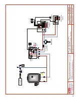
Page 22: ...re relief valves etc for heat source as per local codes Use isolation ball valves for all circuits and components Local codes regulations and authorities have final jurisdiction Rough in wiring see Wiring detail see TWH070P TWH070XP Panel Check Valve in Primary Pump T Thermostat Radiant Heating Manifold Boiler Cold Water Supply SCH TWH M006 2013 03 18 SCH MRIB R001 SCH TWH E006 Boiler TWH Series R...

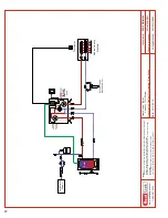
Page 23: ...as per local codes Use isolation ball valves for all circuits and components Local codes regulations and authorities have final jurisdiction Rough in wiring see Wiring detail see Thermostats Thermostat Radiant Heating Manifold Radiant Heating Manifold TWH070P TWH070XP Panel Check Valve in Primary Pump T Boiler Cold Water Supply SCH TWH M007 2013 04 30 SCH MRIB R002 SCH TWH E002 Boiler TWH Series R...

Page 24: ...ief valves etc for heat source as per local codes Use isolation ball valves for all circuits and components Local codes regulations and authorities have final jurisdiction Rough in wiring see Wiring detail see TWH070P TWH070XP Panel Check Valve in Primary Pump T Thermostat SCH TWH M008 2013 04 30 SCH MRIB R001 SCH TWH E001 Tankless Water Heater TWH Series Radiant Floor Heating Single Zone 180 Radi...

Page 25: ...r local codes Use isolation ball valves for all circuits and components Local codes regulations and authorities have final jurisdiction Rough in wiring see Wiring detail see TWH070P TWH070XP Panel Check Valve in Primary Pump T SCH TWH M009 2013 04 30 SCH MRIB R002 SCH TWH E007 Tankless Water Heater TWH Series Radiant Floor Heating Single Zone 180 Cold Water Supply Thermostats Thermostat Radiant He...

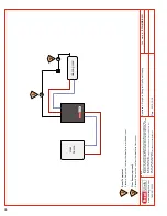
Page 26: ...ch particular control chosen In all cases manufacturer equipment schematics will take precedence over HeatLink electrical schematics Local codes regulations and authorities have final jurisdiction Application Schematic Date Heat Source Heating Load SCH MRIB R001 1 Room Thermostat Standard 4 wire to be run from thermostat to mechanical room 1 2012 10 19 Rough in Wiring for One Zone Heating 2 Floor ...

Page 27: ...ocation SCH MRIB R002 1 1 3 1 Room Thermostats Standard 4 wire to be run from each zone back to the corresponding manifold location 2 Optional Allow for 110V power source to a 24V transformer at each manifold location instead of supplying 24V power from the mechanical room 3 6 wire Jumper 6 wire to be run between each manifold location This allows for the transfer of the clock signal heat demand i...

Page 28: ...manufacturer schematics of each particular control chosen In all cases manufacturer equipment schematics will take precedence over HeatLink electrical schematics Local codes regulations and authorities have final jurisdiction Application Schematic Date Rough in wiring see SCH TWH E001 2013 03 18 Single Zone Heating SCH MRIB R001 W TWHP Panel 24 Vac R C AUX Optional FLWSWTCH DHW Priority Switch FS ...

Page 29: ...acturer equipment schematics will take precedence over HeatLink electrical schematics Local codes regulations and authorities have final jurisdiction Application Schematic Date Rough in wiring see W TWHP Panel 24 Vac R C AUX Optional FLWSWTCH DHW Priority Switch FS L N Secondary Pump Primary Pump 46443 C C R W NTC W R C 1 2 1 1 2 2 C R 24 Vac Class II Transformer Floating Neutral L N 24 V 110V or ...

Page 30: ...cases manufacturer equipment schematics will take precedence over HeatLink electrical schematics Local codes regulations and authorities have final jurisdiction Application Schematic Date Rough in wiring see W TWHP Panel 24 Vac R C AUX Optional FLWSWTCH DHW Priority Switch FS L N Secondary Pump Primary Pump R1 24 Vac SPDT Relay 24 Vac Class II Transformer Floating Neutral L N 24 V 110V or 220V C R...

Page 31: ...n all cases manufacturer equipment schematics will take precedence over HeatLink electrical schematics Local codes regulations and authorities have final jurisdiction Application Schematic Date Rough in wiring see W TWHP Panel 24 Vac R C AUX Optional FLWSWTCH DHW Priority Switch FS L N Secondary Pump Primary Pump R1 24 Vac SPDT Relay 24 Vac Class II Transformer Floating Neutral L N 24 V 110V or 22...

Page 32: ...r control chosen In all cases manufacturer equipment schematics will take precedence over HeatLink electrical schematics Local codes regulations and authorities have final jurisdiction Application Schematic Date Rough in wiring see W TWHP Panel 24 Vac R C AUX Optional FLWSWTCH DHW Priority Switch FS L N Secondary Pump Primary Pump 46443 C C R W NTC SCH TWH E005 2013 03 18 Single Zone Heating SCH M...

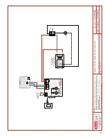
Page 33: ...ematics with manufacturer schematics of each particular control chosen In all cases manufacturer equipment schematics will take precedence over HeatLink electrical schematics Local codes regulations and authorities have final jurisdiction Application Schematic Date Rough in wiring see W TWHP Panel 24 Vac R C AUX L N Secondary Pump Primary Pump SCH TWH E006 2013 04 22 Single Zone Heating SCH MRIB R...

Page 34: ...rol chosen In all cases manufacturer equipment schematics will take precedence over HeatLink electrical schematics Local codes regulations and authorities have final jurisdiction Application Schematic Date Rough in wiring see W TWHP Panel 24 Vac R C AUX L N Secondary Pump Primary Pump 46443 C C R W NTC W R C 1 2 1 1 2 2 C R 24 Vac Class II Transformer Floating Neutral L N 24 V 110V or 220V C R Sta...

Page 35: ... Heat Link 35 www heatlinkgroup com TWH Tankless Water Heater Panels Installation Operation and Maintenance ...

Page 36: ...athay Links International Phone 852 25693213 Fax 852 25359271 Ireland Distributed by Jamoni Ltd Phone 057 932 4062 Fax 057 932 4063 Freephone 1800 311338 México Distributed by Distribuidora Caisa S A de C V Phone 52 55 3300 4400 Fax 52 55 3300 4406 United States Distributed by HeatLink Group Inc USA Distribution Center 1000 100th Street SW Suite B Byron Center MI 49315 Toll Free 1 800 661 5332 Fax...

Reviews: