


14
D. ADJUSTING OR CHECKING FURNACE INPUT
– Natural Gas Line Pressure 5
- 10.5
W.C.
– LP Gas Line Pressure 11
- 13
W.C.
– Natural Gas Manifold Pressure 3.5
W.C
– LP Gas Manifold Pressure - 10
W.C.
S
upply
a
nd m
a
nifold pressure t
a
ps
a
re loc
a
ted on the g
a
s v
a
lve body 1/
8
N.P.T.
a
nd on
the m
a
nifold.
Use
a
properly c
a
libr
a
ted m
a
nometer g
a
uge for
a
ccur
a
te g
a
s pressure re
a
dings.
Only sm
a
ll v
a
ri
a
tions in the g
a
s flow should be m
a
de by me
a
ns of the pressure regul
a
tor
a
djustment. Furn
a
ces functioning on LP g
a
s must be set by me
a
ns of the t
a
nk or br
a
nch
supply regul
a
tors. The furn
a
ce m
a
nifold pressure should be set
a
t 10
W.C.
a
t the g
a
s con-
trol v
a
lve.
To
a
djust the pressure regul
a
tor, remove the regul
a
tor c
a
p
a
nd turn the
a
djustment screw
clockwise to incre
a
se pressure or counterclockwise to decre
a
se pressure.
Then replace
the regulator cap securely.
Any necess
a
ry m
a
jor ch
a
nges in the g
a
s flow r
a
te should be m
a
de by ch
a
nging the size of
the burner orifices. To ch
a
nge orifice spuds, shut off the m
a
nu
a
l m
a
in g
a
s v
a
lve
a
nd
remove the g
a
s m
a
nifold.
For elev
a
tions up to 2,000 feet, r
a
ting pl
a
te input r
a
tings
a
pply. For high
a
ltitudes (elev
a
tions
over 2,000 ft.), see conversion kit index 92-21519-XX for der
a
ting
a
nd orifice spud sizes.
Check of input is important to prevent over-firing of the furnace beyond its design-
rated input. NEVER SET INPUT ABOVE THAT SHOWN ON THE RATING PLATE. Use
the following table or formula to determine input rate.
Heating Value of Gas
(BTU/Cu. Ft.) x 3600
Cu. Ft. Per Hr. Required =
Time in Seconds
(for 1 Cu. Ft.) of Gas
S
t
a
rt the furn
a
ce
a
nd me
a
sure the time required to burn one cubic foot of g
a
s. Prior to
checking the furn
a
ce input, m
a
ke cert
a
in th
a
t
a
ll other g
a
s
a
ppli
a
nces
a
re shut off, with
the exception of pilot burners. Time the meter with only the furn
a
ce in oper
a
tion.
IMPORTANT NOTE FOR ALTITUDES ABOVE 2,000 FEET (610 METERS):
The m
a
in
burner orifices in your furn
a
ce
a
nd in these kits
a
re sized for the n
a
mepl
a
te input
a
nd
intended for inst
a
ll
a
tions
a
t elev
a
tions up to 2,000 feet in the U
S
A or C
a
n
a
d
a
, or for ele-
v
a
tions of 2,000 - 4,500 feet (610 -1,
3
7
3
meters) in C
a
n
a
d
a
if the unit h
a
s been der
a
ted
a
t the f
a
ctory. For elev
a
tions
a
bove 2,000 feet (610 meters)
IN THE USA ONLY
(see
AN
S
I-Z22
3
.1), the burner orifices must be sized to reduce the input 4% for e
a
ch 1,000
feet (
3
05 meters)
a
bove se
a
level.
FIGURE 14
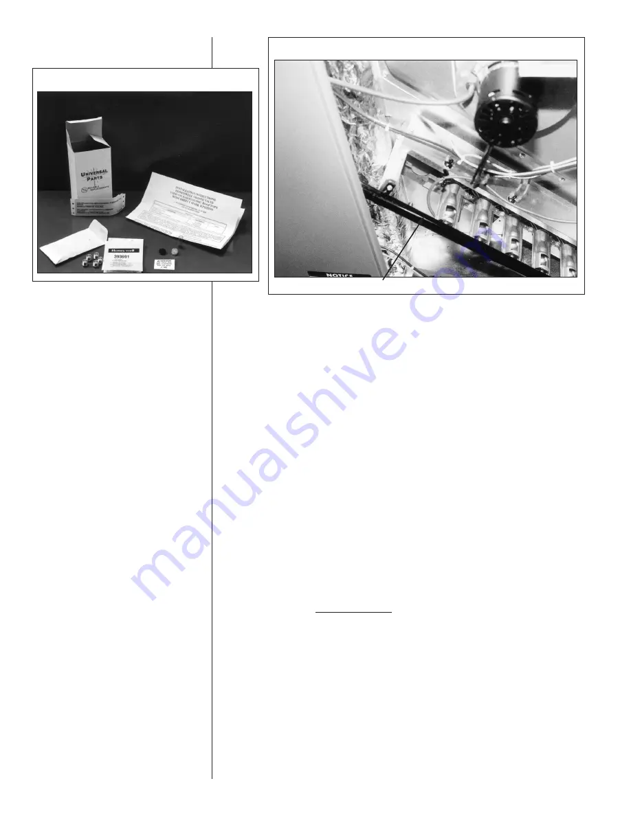
FIGURE 15
MANIFOLD PIPE
Summary of Contents for TGC Series
Page 24: ...24 FIGURE 20 FIGURE 21 INTEGRATED FURNACE CONTROL SPEED TAP BLOCK FIGURE 22...
Page 25: ...25 FIGURE 22 Continued...
Page 37: ...37 FIGURE 23 WIRING DIAGRAM...
Page 38: ...38 FIGURE 24 WIRING DIAGRAM...
Page 39: ...39 FIGURE 25 WIRING DIAGRAM...
Page 40: ...40 FIGURE 26 WIRING DIAGRAM...
Page 41: ...41 FIGURE 27 WIRING DIAGRAM...
Page 42: ...42 FIGURE 28 WIRING DIAGRAM...
Page 43: ...43 FIGURE 29 SYSTEM CHARGE CHARTS 3 TON COOLING 13 SEER...
Page 44: ...44 FIGURE 30 SYSTEM CHARGE CHARTS 3 5 TON COOLING 13 SEER...
Page 45: ...45 FIGURE 31 SYSTEM CHARGE CHARTS 4 TON COOLING 13 SEER...
Page 46: ...46 FIGURE 32 SYSTEM CHARGE CHARTS 5 TON COOLING 13 SEER...
Page 50: ...50...
Page 51: ...51...
Page 52: ...52 CM 1206...


