


12
VIII. GAS SUPPLY, CONDENSATE DRAIN AND
VIII.
PIPING
A. GAS CONNECTION
IMPORTANT:
Connect this unit only to g
a
s supplied by
a
commerci
a
l utility.
1. Inst
a
ll g
a
s piping in
a
ccord
a
nce with loc
a
l codes
a
nd regul
a
tions of the loc
a
l utility
comp
a
ny. In the
a
bsence of loc
a
l codes, the inst
a
ll
a
tion must conform to the specifi-
c
a
tions of the N
a
tion
a
l Fuel G
a
s Code, AN
S
I Z22
3
.1 - l
a
test edition.
NOTE: The use of flexible g
a
s connectors is not permitted.
2. Connect the g
a
s line to the g
a
s pipe inlet opening provided into the 1/2
inlet v
a
lve.
S
ee Figure 5 or
8
for typic
a
l piping.
3
.
S
ize the g
a
s line to the furn
a
ce
a
dequ
a
te enough to prevent undue pressure drop
a
nd never less th
a
n 1/2
.
4. Inst
a
ll
a
drip leg or sediment tr
a
p in the g
a
s supply line
a
s close to the unit
a
s possi-
ble.
5. Inst
a
ll
a
n outside ground joint union to connect the g
a
s supply to the control
a
ssem-
bly
a
t the burner tr
a
y.
6. G
a
s v
a
lves h
a
ve been f
a
ctory inst
a
lled. Inst
a
ll
a
m
a
nu
a
l g
a
s v
a
lve where loc
a
l codes
specify
a
shut-off v
a
lve outside the unit c
a
sing. (
S
ee Figure 1
3
.)
NOTE:
The Commonwe
a
lth of M
a
ss
a
chusetts requires the g
a
s shut-off v
a
lve to be
a
T-
h
a
ndle g
a
s lock.
7. M
a
ke sure piping is tight.
A pipe compound resistant to the action of liquefied
petroleum gases must be used at all threaded pipe connections.
8
. IMPORTANT:
a
ny
a
dditions, ch
a
nges or conversions required for the furn
a
ce to s
a
t-
isf
a
ctorily meet the
a
pplic
a
tion should be m
a
de by
a
qu
a
lified inst
a
ller, service
a
gency or the g
a
s supplier, using f
a
ctory-specified or
a
pproved p
a
rts. In the com-
monwe
a
lth of M
a
ss
a
chusetts, inst
a
ll
a
tion must be performed by
a
licensed plumber
or g
a
s fitter for
a
ppropri
a
te fuel.
IMPORTANT:
Disconnect the furn
a
ce
a
nd its individu
a
l shutoff v
a
lve from the g
a
s sup-
ply piping during
a
ny pressure testing of th
a
t system
a
t test pressures in excess of 1/2
pound per squ
a
re inch g
a
uge or isol
a
te the system from the g
a
s supply piping system
by closing its individu
a
l m
a
nu
a
l shutoff v
a
lve during
a
ny pressure testing of this g
a
s sup-
ply system
a
t pressures equ
a
l to or less th
a
n 1/2 P
S
IG.
TO CHECK FOR GAS LEAKS, USE A SOAP AND WATER SOLUTION OR OTHER
APPROVED METHOD. DO NOT USE AN OPEN FLAME.
IMPORTANT:
Check the r
a
ting pl
a
te to m
a
ke cert
a
in the
a
ppli
a
nce is equipped to burn
the type of g
a
s supplied. C
a
re should be t
a
ken
a
fter inst
a
ll
a
tion of this equipment th
a
t
the g
a
s control v
a
lve not be subjected to high g
a
s supply line pressure.
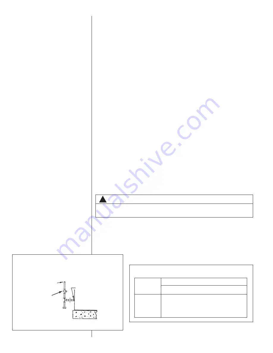
FIGURE 13
SUGGESTED GAS PIPING
FROM GA
S
METER
*
F
a
ctory supplied grommet must be utilized.
MANUAL GA
S
S
HUT-OFF
VALVE
UNIT GA
S
S
UPPLY
CONNECTION
*
ROOF OR GROUND LEVEL INSTALLATION
!
WARNING
CHECK FOR LEAKS. THE USE OF AN OPEN FLAME CAN RESULT IN FIRE,
EXPLOSION, PROPERTY DAMAGE, PERSONAL INJURY OR DEATH.
Nomin
a
l
Iron Pipe
S
ize,
Inches
Equiv
a
lent Length of Pipe, Feet
10
20
3
0
40
50
60
70
8
0
1
⁄
2
1
3
2
92
7
3
6
3
56
50
46
4
3
3
⁄
4
27
8
190
152
1
3
0
115
105
96
90
1
520
3
50
2
8
5
245
215
195
1
8
0
170
1
1
⁄
4
1,050
7
3
0
590
500
440
400
3
70
3
50
1
1
⁄
2
1,600 1,100
8
90
760
670
610
560
5
3
0
TABLE 1
GAS PIPE CAPACITY TABLE (CU. FT./HR.)
Summary of Contents for TGC Series
Page 24: ...24 FIGURE 20 FIGURE 21 INTEGRATED FURNACE CONTROL SPEED TAP BLOCK FIGURE 22...
Page 25: ...25 FIGURE 22 Continued...
Page 37: ...37 FIGURE 23 WIRING DIAGRAM...
Page 38: ...38 FIGURE 24 WIRING DIAGRAM...
Page 39: ...39 FIGURE 25 WIRING DIAGRAM...
Page 40: ...40 FIGURE 26 WIRING DIAGRAM...
Page 41: ...41 FIGURE 27 WIRING DIAGRAM...
Page 42: ...42 FIGURE 28 WIRING DIAGRAM...
Page 43: ...43 FIGURE 29 SYSTEM CHARGE CHARTS 3 TON COOLING 13 SEER...
Page 44: ...44 FIGURE 30 SYSTEM CHARGE CHARTS 3 5 TON COOLING 13 SEER...
Page 45: ...45 FIGURE 31 SYSTEM CHARGE CHARTS 4 TON COOLING 13 SEER...
Page 46: ...46 FIGURE 32 SYSTEM CHARGE CHARTS 5 TON COOLING 13 SEER...
Page 50: ...50...
Page 51: ...51...
Page 52: ...52 CM 1206...


