background image

A1813-1.1 en

TEDS-

memory module in  
transducer -
Content and editing
the memory module

Operating Manual

Summary of Contents for TEDS

Page 1: ...A1813 1 1 en TEDS memory module in transducer Content and editing the memory module Operating Manual...

Page 2: ......

Page 3: ...main templates 12 4 1 Basic TEDS 13 4 2 Templates for definition of transducer type 13 4 3 Optional templates 20 4 4 Other templates 23 5 Examples for operating with TEDS 24 5 1 Example 1 24 5 2 Exam...

Page 4: ...n instructed to carry out the installation commissioning maintenance or repair of the transducer TEDS module and amplifier must have read and understood the Operating Manual and in particular the tech...

Page 5: ...ir or soldering work on motherboards is prohibited Qualified personnel This module is only to be installed and used by qualified personnel strictly in accordance with the specifications and within the...

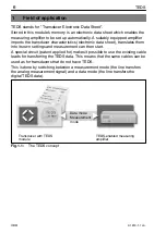
Page 6: ...into its own settings and measurement can then start A special circuit patent applied for makes it possible to use the existing cable leads for transferring the TEDS data This means that the same cabl...

Page 7: ...contains characteristic transducer data that can be defined by the manufacturer by calibration or by the user They are organized into so called templates which store defined groups of data in a summa...

Page 8: ...one entry to the next within a template Standard rights USR level This level concerns rights that the operator of the transducer needs in order to change entries which depend on the conditions of use...

Page 9: ...manufacturer specific it is recommended for compatibility reasons always to arrange the manufacturer specific templates in the TEDS memory after all templates which meet the IEEE 1451 4 standard Other...

Page 10: ...odule NOTE If the user rights in levels CAL or IDENT are used there is a danger of unintentional overwriting of the central transducer data 3 3 1 Editing TEDS in the HBM view The HBM view is orientate...

Page 11: ...or low pass filtering tare or zero value This data is optional if no values are entered in TEDS the respective settings of the amplifier are retained when reading in the TEDS data Units conversion HBM...

Page 12: ...etely new TEDS contents the individual templates must first be generated via the command sequence Edit New New template The minimum requirement is at least one template created that describes the resp...

Page 13: ...be shown in plain text Version letter ID Possible values a letter from A to Z Version number 7 ID Possible values a number from 0 to 63 The serial number positions that precede the last 7 places for...

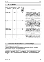
Page 14: ...e 1 999m V V CAL ues is the sensitivity according to the HBM test certificate and from calibration Mapping Method Linear This entry cannot be changed Bridge type Full ID The bridge type The following...

Page 15: ...Feb Mar Apr May Jun Jul Aug Sep Oct Nov Dec Calibration Initials HBM CAL Initials of the calibrator or calibration laboratory concerned Calibration Period Days 730 days CAL Time before recalibration c...

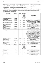
Page 16: ...test certificate or from calibration Mapping Method Linear This entry cannot be changed Bridge type Full The bridge type The following values are available for selection Quarter for quarter bridge Ha...

Page 17: ...e used Format day month year Abbreviations for the months Jan Feb Mar Apr May Jun Jul Aug Sep Oct Nov Dec Calibration Initials HBM CAL Initials of the calibrator or calibration laboratory concerned Ca...

Page 18: ...eters and units are de fined when the template is created Pulse Measurement Type Frequency CAL Measuring mode frequency measurement or pulse counting Minimum Electrical Value 0 0 Hz CAL The difference...

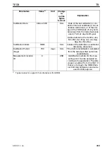
Page 19: ...ID Upper limit for the operat ing range of the excitation voltage according to the HBM data sheet Excitation Voltage Type Bipolar DC ID This entry cannot be changed Excitation Current Draw 300 000u A...

Page 20: ...the lowpass filter This has the advantage for users who prefer to carry out a manual zero balance that the Zero Compensation Value parameter will not be overwritten next time the TEDS memory is import...

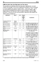
Page 21: ...urve segments 1 Elements CAL 1 Starting domain value of segment of full span 0 CAL Calibration curve polynomial 3 Elements CAL 1 Power of domain value 1 1 0 CAL y a1x1 a2x2 a3x3 Power for the first po...

Page 22: ...n table 3 Elements CAL contains 3 points of the characteristic curve Elements 1 Domain Calibration Point of full span 0 00 CAL of full span 1 Range Calibration deviation of full span 0 0030 CAL Percen...

Page 23: ...escribe other transducer types TEDS enabled HBM amplifiers currently recognize the following templates from this group High Level Voltage Output Sensors Transducers with voltage output Resistance Sens...

Page 24: ...5 AP455i MGC connected to PC via e g USB or Ethernet Operated via PC software catman Easy When starting catmanEasy check that the option Sensor Scan is activated During booting up catman Easy automati...

Page 25: ...asy component on the Signal processing tab This creates an additional HBM specific template which can then only be interpreted by HBM measuring amplifiers It is ignored by other measuring amplifiers N...

Page 26: ...o the TEDS memory of the transducer Changes are possible at a later date MGC connected to PC e g USB or Ethernet interface PC has the MGCplus Assistant software included in the MGC scope of delivery a...

Page 27: ...annel that the TEDS transducer is connected to here Channel 3 In the subsequent context menu select the menu item Edit TEDS This starts the TEDS Editor Step II in the TEDS Editor Click on HBM view Lef...

Page 28: ...and enter the calibration initials to identify the person or body that implemented the calibration Enter the recalibration deadline following the quality management guidelines at the operator in days...

Page 29: ...The general unit bar is not supported because of the Standard IEEE 1451 4 However to display the unit bar the additional HBM specific Template Unit Conversion is used This is available by default and...

Page 30: ...in the column Zero value Tare value or zero using the displayed button NOTE A zero adjustment is generally not stored in the TEDS memory as this is dependent on the installation situation of the tran...

Page 31: ...2 1 Setting up via the AB22A display control panel Connect the transducer to the measuring device Display the channel to which the TEDS transducer is connected on the display select with the channel...

Page 32: ...suring device Start the Assistant can also be implemented before connecting the transducer Select the channel to which the TEDS transducer is connected in the Assistant view Transducer see Page 27 Rig...

Page 33: ...inal value of supply voltage for TEDS data memory V 5 Working range of supply voltage for TEDS data memory V 3 4 6 0 Data transfer protocol As specified in IEEE standard 1451 4 one wire protocol Data...

Page 34: ...34 TEDS A1813 1 1 en HBM...

Page 35: ...35 TEDS A1813 1 1 en HBM...

Page 36: ...45 D 64293 Darmstadt Germany Tel 49 6151 8030 Fax 49 6151 80 39 100 E mail support hbm com www hbm com Modifications reserved All details describe our products in general form only They are not to be...

Reviews: