


31
T12
A1979
−
10.0 en
HBM
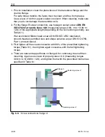
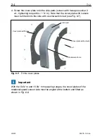
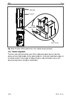
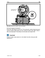
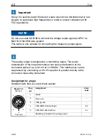
Spacer
Transmitter rotor
Alignment line
Fig. 6.16:
Axial alignment to the rotor
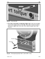
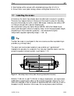
6. Connect the power line (plug 1 or plug 3). Notice the LED to the right of
plug 4. The stator is correctly aligned, when the LED successively
flashes red for about 10 seconds
flashes yellow for about 10 seconds
then stays permanently green (CAN Bus) or yellow or green
(PROFIBUS).
When data are being exchanged via the CAN Bus or the PROFIBUS, the LED
flashes green.
You can also use the T12 Assistant to check for the correct alignment. The
LED must stay green in the “Rotor clearance setting mode”.
7. Now fully tighten the fastening screws (tightening torque 14 N
@
m).
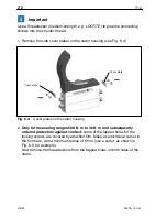
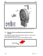
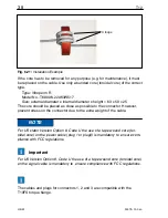
8. Remove the spacers, by first removing the adhesive strip and then the red
plastic strip.
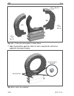
9. Make sure that the air gap between the rotor and
stator is free from
electrically conductive and other foreign matter.
Summary of Contents for T12
Page 1: ...A1979 10 0 en Digital Torque Transducer T12 Mounting Instructions ...
Page 2: ......
Page 89: ...89 T12 A1979 10 0 en HBM ...
Page 90: ...T12 90 A1979 10 0 en HBM ...
Page 91: ......


