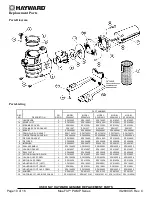


USE ONLY HAYWARD GENUINE REPLACEMENT PARTS
Page 5 of 16
Max-Flo™ PUMP Series
IS2800X5 Rev. C
Allow adequate access for servicing pump and piping.
Incorporate a straight portion of pipe prior to pump inlet no less than (5) pipe diameters in length.
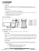
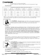
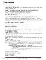
Pipe Sizing Chart
MAXIMUM RECOMMENDED SYSTEM FLOW RATE BY PIPE SIZE
Pipe Size
Flow rate
Water Velocity
Pipe Size
Flow rate
Water Velocity
inches [mm]
GPM [Liter/Min]
ft/sec [meters/sec]
inches [mm]
GPM [Liter/Min]
ft/sec [meters/sec]
1 ½”
50.76
8
2 ½”
119.40
8
[50]
[192]
[2.44]
[75]
[452]
[2.44]
2”
83.65
8
3”
184.32
8
[63]
[317]
[2.44]
[90]
[698]
[2.44]
NOTE
– No system should allow any higher than 8-ft/sec [2.44 meters/sec] water velocity. It is recommended that a minimum
length of piping, equivalent to 10 pipe diameters, be used between the pump suction inlet and any plumbing fittings.
WARNING –
Hazardous Pressure.
Pumps, filters, and other equipment/ components of a
swimming pool filtration system operate under pressure. Incorrectly installed and/or improperly tested
filtration equipment and/or components may fail resulting in injury and/or property damage.
Plumbing
Use
Teflon tape
to seal threaded connections on molded plastic components. All plastic fittings must be new or thoroughly
cleaned before use.
NOTE - Do NOT use Plumber’s Pipe Dope as it may cause cracking of the plastic components.
When applying
Teflon tape
to plastic threads, wrap the entire threaded portion of the male fitting with one to two layers of
tape. Wind the tape clockwise as you face the open end of the fitting, beginning at the end of the fitting. The pump suction
and outlet ports have molded-in thread stops.
Do NOT attempt to force hose connector fitting past this stop.
It is only
necessary to tighten fittings enough to prevent leakage. Tighten fitting by hand and then use a tool to engage fitting an
additional 1 ½ turns. Use care when using Teflon tape as friction is reduced considerably;
do NOT over-tighten fitting or
you may cause damage
. If leaks occur, remove connector, clean off old Teflon tape, re-wrap with one to two additional
layers of Teflon tape, and re-install connector.
Fittings
Fittings restrict flow. For better efficiency, use the fewest possible fittings (but at least two suction outlets). Avoid fittings
that could cause an air trap. Pool and spa fittings MUST conform to the International Association of Plumbing and
Mechanical Officials (IAPMO) standards.
Use a non-entrapping suction fitting in pool (multiple drains) or double suction
(skimmer and main drain).
Electrical
WARNING –
All wiring must be done by a licensed electrician and must conform to all
local and national codes and regulations.
WARNING –
Ground and bond motor before connecting to electrical power supply. Failure
to ground and bond pump motor can cause serious or fatal electrical shock hazard.
WARNING –
Do NOT ground to a gas supply line.
WARNING –
To avoid dangerous or fatal electrical shock, turn OFF power to motor before
working on electrical connections.
WARNING –
Ground Fault Circuit Interrupter (GFCI) tripping indicates electrical problem. If GFCI trips and
won’t reset, consult electrician to inspect and repair electrical system.
WARNING –
Fire Hazard.
Match supply voltage to motor nameplate voltage.


