Hayward EcoStar SP3400VSP, Technical Installation Manual
Introducing the Hayward EcoStar SP3400VSP, a cutting-edge pool pump designed to provide maximum energy efficiency. For your convenience, a comprehensive Technical Installation Manual is available for free download at manualshive.com. This invaluable manual ensures a hassle-free installation and optimal performance, giving you peace of mind.
Share
Download


Reviews:
No comments
Related manuals for EcoStar SP3400VSP
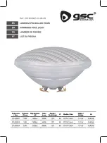
201400002
Brand: GSC Pages: 14

SLPORBT36
Brand: SereneLife Pages: 10

PROWLER 920
Brand: Pentair Pages: 44

BADU 90
Brand: Speck pumpen Pages: 124

POOLDENS 100T
Brand: COSMOGAS Pages: 96

Alpha iQ
Brand: Polaris Pages: 84

Nitro XL NC31XL
Brand: SmartPool Pages: 6

PT9i
Brand: SmartPool Pages: 16

PT7i
Brand: SmartPool Pages: 16

Aquabot
Brand: Aqua Products Pages: 8

Pool Rover T E1595
Brand: Aqua Products Pages: 16

DV4000
Brand: Hayward Pages: 24

EVEN GLOW
Brand: PAL Pages: 5

PM400PV
Brand: Davey Pages: 20

Silensor SLL1200F
Brand: Davey Pages: 72

StarFlo DSF150
Brand: Davey Pages: 84

Low NOx 525
Brand: Pentair Pages: 104

Rapid Kleen 26"
Brand: Watermaid Pages: 8


