background image

2.5

2.5

PARTS DIAGRAM

2.5

2.5

116

117

37

149

1D396D01A

9

4

3

1

24

128

25

2

4

26

116

130

27

70

63

136

136

135

68

68

33

49

72

63

14

60

62

15

13

49

58

62

59

57

51

64

35

65

16

50

125

54

87

11

17

89

122

121

122

47

47

48

48

55

143

124

124

108

107

106

127

53

53

109

110

129

92

92

142

90

90

15

93

93

98

98

98

98

104

102

103

103

98

98

120

102

102

102

101

126

144

36

54

73

56

40

43

40

40

131

118

137

125

40

40

29

27

30

31

32

84

67

18

18

76

78

78

115

79

79

80

80

133

132

77

134

77

94

81

82

82

139

83

83

78

78

140

140

38

38

61

61

138

18

18

6

6

34

34

44

44

148

140

146

61

140

145

147

61

18

105

105

18

18

18

46

86

41

28

28

42

42

39

39

40

40

20

20

139

132

18

71

133

21

21

22

22

40

40

85

69

85

7

12

23

5

10

67

140

52

19

134

112

111

75

74

113

114

150

151

123

150

151

18

71

115

66

97

91

97

91

119

119

98

95

96

88

88

95

96

100

142

45

99

51

51

51

8

49

46

13

86

123

157

152

152

159

156

154

158

155

161

111-0445(A)  21/10/05  10:26 am  Page 2.5

Summary of Contents for Ranger 53 Pro 396D

Page 1: ... English Version FROM SERIAL NO Code 396D 250000001 Issue 17 10 05 HANDBOOK 111 0445 A OWNER S HANDBOOK Ranger 53 Pro CODE 396D 111 0445 A 21 10 05 10 26 am Page 1 ...

Page 2: ...111 0445 A 21 10 05 10 26 am Page 2 ...

Page 3: ...me Serial Number Date 2nd Year 24 months We certify that this service has been carried out by an Authorised Hayter Service Dealer Date Owner s Name Serial Number Date Note for dealer Please retain this voucher for your records Note for dealer Please retain this voucher for your records 2nd Year 24 months 111 0445 A 21 10 05 10 26 am Page 1 1 ...

Page 4: ...111 0445 A 21 10 05 10 26 am Page 1 2 ...

Page 5: ...oss non grassed areas Cutterbar operation Mowing and grass care tips MAINTENANCE Engine Grassbag Deck housing Securing nuts and bolts Lubrication Clutch cable adjustment Cutterbar Maintenance Schedule PREPARING THE MOWER FOR STORAGE FAULT FINDING DECLARATION OF CONFORMITY 396 PARTS LIST 396 PARTS DIAGRAM ENGINE ANCILLARY PARTS NOTES CUSTOMER INFORMATION 1 4 1 5 1 6 1 9 1 9 1 10 1 11 1 11 1 12 1 14...

Page 6: ...ed only by persons who are familiar with its particular characteristics and who are acquainted with the relevant safety procedures The safety precautions listed herein and all other generally recognised regulations on safety must be observed at all times All Hayter mowers are robustly constructed and designed for efficient economical performance under normal mowing conditions Correct operation and...

Page 7: ...units and other such devices are not applicable Only machines fitted with a genuine Hayter friction disc or crankshaft support bearing which are used in accordance with the recommended operating and maintenance procedures are covered This warranty does not apply to any unit that has been tampered with altered misused abused or used for hire and will become invalid if non genuine Hayter parts are f...

Page 8: ...gned for this purpose Refuel outdoors only and do not smoke while refuelling Add fuel before starting the engine Never remove the cap from the fuel tank or add petrol while the engine is running or when the engine is hot Allow engine to cool for at least 2 min utes before refuelling Do not attempt to start the engine if petrol is spilled or a smell of petrol is present but move the mower away from...

Page 9: ... the guards are securely in position and in good condition Do not change the engine governor settings or overspeed the engine Disengage the drive clutch before starting the engine Replace all fuel tank caps and fuel container caps securely Replace faulty exhaust and mufflers Always ensure that the mower is in a safe operating condition Frequently check all nuts bolts and screws for tightness Use o...

Page 10: ...lockages or unclogging the discharge chute Before cleaning checking or working on the mower Stop the engine Do not lift the rear deflector whilst the mower is in operation Whenever you leave the mower Before refuelling After striking a foreign object Inspect the mower for damage and make repairs before restarting and operating the mower If the mower starts to vibrate abnormally check immediately W...

Page 11: ...rassbag frequently for wear or deterioration Replace worn or damaged parts for safety Use genuine Hayter parts only If the fuel tank has to be drained it is essential that this be done outdoors DECALS WARNING DECAL DANGER OF BEING HIT BY THROWN OBJECTS KEEP BYSTANDERS AT A SAFE DISTANCE FROM THE MACHINE WARNING CAUTION RISK OF DANGER SAFETY ALERT DANGER OF SEVERING TOES OR FINGERS IN CUTTING MECHA...

Page 12: ...5 x 585 x 1025mm 60 5 Kg NGK BCP5RES CHAMPION RC12Y2 0 50mm SPECIFICATIONS SPECIFICATIONS Engine Engine type Engine cutterbar speed Fuel type Fuel capacity Oil type Oil sump capacity Cutting width Cutting height Overall dimensions Dry Weight Spark Plug Spark Plug Gap CODE 396 SG56 RC VAR PRO MODELS 111 0445 A 21 10 05 10 26 am Page 1 10 ...

Page 13: ...1 12 13 14 15 16 17 18 8 1 Spark Plug Lead 2 Primer Bulb 3 Engine Cover 4 Air Filter 5 Fuel Filler Cap 6 Oil Filler Cap Dipstick 7 Height of Cut Lever 8 Serial No Label 9 Rear Deflector 10 Handlebar Securing Knob 11 Engine Start Grip 12 Throttle Control 13 Lever Engine Stop 14 Handlebar 15 Ground Drive Clutch Lever 16 Ground Drive Speed Control 17 Grassbag Assembly 18 Muffler Guard 111 0445 A 21 1...

Page 14: ...Handlebar Cap Cable Guide Grassbag Frame Grassbag Fabric Grassbag Flap Engine Handbook DELIVERY CHECKLIST ASSEMBLING THE MOWER FOR THE FIRST TIME ASSEMBLY INSTRUCTIONS Quantity 1 1 4 4 4 1 1 4 1 4 4 1 1 1 1 Assemble the handlebars Assemble the handlebars as shown Route the cables carefully and clip in position to avoid damage and entanglement when using the machine CAUTION PREVENT DAMAGE When asse...

Page 15: ...ING PREVENT ACCIDENTS Always ensure grassbag flap is securely fitted and in good condition Raise the rear deflector and lower the grassbag through the handlebar aperture to connect onto the upper mounting points Lower the grassbag to rest against the rear of the mower Ensure the grassbag flap is closed Finally lower the rear deflector to rest against the top of the grassbag CS221 CS226 111 0445 A ...

Page 16: ...ves freely and that the lever returns automatically to the engine stop position when released CS214 CS232 Check throttle lever operation Operate the throttle lever several times and ensure the cable moves freely whilst operating the engine throttle mechanism Check clutch lever operation Operate the clutch lever several times and ensure that the cable moves freely CS015 CS212 111 0445 A 21 10 05 10...

Page 17: ...imperative that the oil level is checked more frequently if this grade of oil is used in order to guard against serious engine damage Check oil level Clean around the oil filler cap before remov ing With the mower on a level surface unscrew and remove the oil filler dipstick Wipe oil from it with a clean cloth Screw the oil filler dipstick back in place then unscrew and remove it to check the oil ...

Page 18: ... tank with clean unleaded petrol Do not overfill the fuel tank Allow 6mm minimum of tank space for fuel expansion IMPORTANT The fuel filler cap must be secured to pre vent fuel leakage during operation WARNING PREVENT ACCIDENTS The cutterbar rotates when the engine is operating ALWAYS operate the engine stop lever several times and ensure the engine stop cable moves freely before starting the engi...

Page 19: ...inst the handlebar To start and operate the engine the engine stop lever must be held in the operating position If the engine stop lever is released the engine will stop Operate the engine start grip Stand behind the mower and maintain a firm hold on the handlebar and the engine stop lever to prevent the mower moving towards you Use your right hand to hold the engine start grip and pull slowly unt...

Page 20: ...ing the engine stop lever STOP CS215 STOPPING THE ENGINE SAFETY NOTICE OPERATING THE MOWER WARNING PREVENT ACCIDENTAL STARTING Always stop the engine and disconnect the spark plug lead before cleaning inspecting or working on the machine CS229 1 STOP 3 2 CS229 1 STOP 3 2 1 Engine 2 Spark Plug Lead 3 Spark Plug 1 Engine 2 Spark Plug Lead 3 Spark Plug 111 0445 A 21 10 05 10 26 am Page 1 18 ...

Page 21: ...id ing low cuts in long grass conditions Be prepared to make two cuts when the grass is long WARNING PREVENT ACCIDENTS Before mowing thoroughly inspect the area where the mower is to be used and remove all stones sticks wires bones and other foreign objects which when contacted by the mower cutterbar could become dangerous projectiles Inspect the area for hidden obstructions which when contacted b...

Page 22: ...p the engine running Reverse Travel Release the clutch lever Hold and pull against the handlebar with both hands to reverse the mower towards you OPERATING THE MOWER WARNING PREVENT ACCIDENTS Always reverse the mower carefully towards you Always switch off the engine before walking backwards with the mower TRAVEL TURNING THE MOWER To make a wide turn Steer the mower with the handlebar whilst trave...

Page 23: ...s bag through the handlebar aperture to connect onto the upper mounting points Lower the grassbag to rest against the rear of the mower Ensure grassbag flap is closed Finally lower the rear deflector to rest against the top of the grassbag Grassbag removal Raise the rear deflector and lift the grassbag through the handlebar aperture and away from the mower Finally lower the rear deflector to rest ...

Page 24: ... growth should be mown without grass collec tion If grass collection is required first mow the area without grass collection at the maximum height of cut setting Allow the grass clippings to dry out and then mow the area at the max imum height of cut setting with the grassbag fitted Reduce the height of cut and mow the area again as necessary until the required finish is obtained WARNING PREVENT A...

Page 25: ...ct the spark plug lead and examine the cutting mechanism ALWAYS replace a damaged cutterbar refer to Maintenance The cutterbar rotates at the same speed as the engine The cut terbar will stop within three seconds of the engine being switched off WARNING PREVENT ACCIDENTS DO NOT operate the mower if the cutterbar fails to stop within three seconds Return the mower to your Hayter dealer for exami na...

Page 26: ...he grass is weed free leave the clippings on the lawn to help main tain ground moisture Mow lawns twice a week when the grass is growing vigorously in the summer Mow lawns once a week in spring autumn and during prolonged dry weather in the summer OPERATING THE MOWER 32mm 38mm 25mm 19mm 12mm 6mm Prevent grass damage DO NOT remove more than one third of the grass height in one cut Recommended grass...

Page 27: ...s handbook supplied with your mower ENGINE GRASSBAG Remove grass debris from the grassbag immediately after use and check its condition for signs of damage DECK HOUSING Remove grass debris from the deck housing and around the engine immediately after use IMPORTANT PREVENT DAMAGE Fertilisers and top dressings are particularly corrosive Thoroughly clean the mower deck immediately after use on treate...

Page 28: ...ck that all securing nuts and bolts are tight Replace missing or damaged items immediately CS022 CS015 CLUTCH CABLE ADJUSTMENT Check the clutch cable operation every 25 operating hours and adjust if necessary Unscrew locknut 1 and screw adjuster 2 in or out as necessary Tighten locknut when correctly adjusted IMPORTANT PREVENT DAMAGE ALWAYS operate the mower with the clutch cable correctly adjuste...

Page 29: ...ng the cutterbar is tightened to the specified torque of 40Nm Replace the cutterbar every season or sooner if excessively worn or damaged How to remove the cutterbar Drain the fuel by operating the engine until the fuel tank is empty and the engine stops Remove the spark plug lead and allow the engine to cool Turn the mower on its left hand side and ensure that the air cleaner side of the engine i...

Page 30: ...the cutterbar for signs of damage DO NOT use a damaged or excessively worn cutterbar Sharpen all the cutting edges with a flat file to restore the original cutting edge Ensure that the cutterbar is balanced Use a screw driver with a round shaft to support the cutterbar through its centre hole Hold the cutterbar horizontal and then release A balanced cutterbar will remain horizontal If the cutterba...

Page 31: ...r ways in the top cowl Remove grass debris from top and underside of deck housing Remove grass debris from the grassbag and check for signs of damage Check condition of guards and safety devices Check condition of cutterbar Change engine oil if continuously operating under heavy load or high ambient temperature Lubricate wheels pivot points and linkages Grease inner control cables at point of entr...

Page 32: ...l Clean engine cooling system Clean more often under dusty conditions or when air borne debris is present or after prolonged operation whilst cutting tall dry grass Service the dual element air cleaner cartridge Replace spark plug EVERY 100 HOURS OR EVERY SEASON 111 0445 A 21 10 05 10 26 am Page 1 30 ...

Page 33: ...nto the engine cylinder and replace the spark plug Do not exceed the stated vol ume of oil as engine damage may occur on re starting Do not replace the spark plug lead Operate the engine stop lever and slowly pull the engine start grip once to crank the engine This will distribute the oil and help prevent engine corrosion Clean grass and debris from the engine cylinder cylinder head cooling fins u...

Page 34: ...in fuel tank and fill with correct fuel Connect spark plug lead Operate engine stop lever Clean and adjust gap or replace Connect spark plug lead Clean and adjust gap or replace Replace air cleaner element Drain fuel tank and fill with correct fuel Tighten bolts Tighten bolt Balance cutterbar Engine will not turn over Engine stop lever released Operate engine stop lever Incorrect oil level Check o...

Page 35: ...harge chute blocked Wet grass Grassbag full FAULT FINDING Uneven cut Discharge chute blocks Mower is hard to push Mower will not self propel Poor grass collection Change direction of travel Sharpen the cutterbar Balance cutterbar Inspect and replace as neces sary Mow dry grass Increase cut height Empty grassbag Clean the grassbag Increase height of cut Inspect and lubricate or replace as necessary...

Page 36: ... regulations transposed into national law Also Directive 2000 14 EC Noise emission in the environment by equipment for use outdoors and the regula tions transposed into national law procedure applied for the conformity assessment Annex VI procedure 1 Notified Body NOVICOM SAS DI R CASTELLI CO Via della Fontana 23804 Monte Marenzo LC Notified body identification No 0723 Measured sound power level 9...

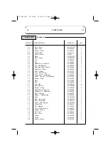
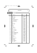
Page 37: ...013540 1 16 Cover Variable Pulley SA480190 1 17 Spring Rear Deflector see item 121 1 18 Bearing SA203560 10 19 Decal Height of Cut 320006 1 20 Gear Rear Wheel SA496770 2 21 Cover Wheel SA380570 2 22 Washer Plain SA150770 4 23 Deck SA380390 1 24 Key SA101370 1 25 Boss Pulley SA2010190 1 26 Washer Bellville SA2006400 2 27 Washer Large SA3006420 2 28 Screw M12 x 75 SA1013980 2 29 Blade SA280520 1 30 ...

Page 38: ...ing SA172850 2 58 Washer Plain SA181690 2 59 Bolt SA172960 1 60 Bolt SA184540 1 61 Cap Hub SA380740 4 62 Bolt Special SA3021890 2 63 Washer Fixing SA145900 4 64 Handlebar Lower L H SA380290 1 65 Support L H Handlebar SA380300 1 66 Flap Grassbag SA480400 1 67 Spring Compensating SA280160 1 68 Screw SA1015560 3 69 Rod Connecting SA3037780 1 70 Strip Protection SA380970 1 71 Screw Self Tapping SA1012...

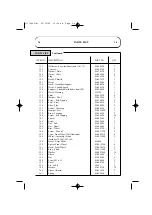
Page 39: ... 14 99 Plate Blanking SA380690 1 100 Cover SA480660 1 101 Cover SA480840 1 102 Screw Self Tapping SA185610 6 103 Screw Self Tapping SA185620 4 104 Cover SA480820 1 105 Wheel Front SA3012050 2 106 Spacer Ground Drive Cable SA460260 1 107 Spring Ground Drive Cable SA262090 1 108 Cable Ground Drive SA2013880 1 109 Cable Engine Stop SA2011320 1 110 Cover SA480640 1 111 Gearbox SA280230 1 112 Spring Te...

Page 40: ...9560 1 138 Bumper Bar SA3016080 1 139 Ring Locating SA396620 2 140 Screw Self Tapping SA184950 28 141 Spacer SA285480 2 142 Screw SA142450 2 143 Nut Full SA142000 1 144 Nut Dome SA106440 1 145 Rim Wheel SA380750 2 146 Screw M6 x 20 SA1017230 2 147 Caps Front Wheel Not Illustrated SA3006310 2 148 Wheel Assembly Front SA3013940 2 Includes 18 38 61 105 145 149 Decal Grass Blade 410064 1 150 Spacer Fr...

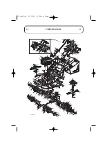
Page 41: ...4 73 56 40 43 40 40 131 118 137 125 40 40 29 27 30 31 32 84 67 18 18 76 78 78 115 79 79 80 80 133 132 77 134 77 94 81 82 82 139 83 83 78 78 140 140 38 38 61 61 138 18 18 6 6 34 34 44 44 148 140 146 61 140 145 147 61 18 105 105 18 18 18 46 86 41 28 28 42 42 39 39 40 40 20 20 139 132 18 71 133 21 21 22 22 40 40 85 69 85 7 12 23 5 10 67 140 52 19 134 112 111 75 74 113 114 150 151 123 150 151 18 71 11...

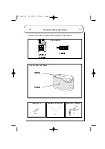
Page 42: ...ARK PLUG SPARK PLUG WRENCH SPARK PLUG TESTER AIR CLEANER CARTRIDGE FUEL ADDITIVE These parts are available through an authorised Briggs Stratton dealer ENGINE ANCILLARY PARTS 111 0445 A 21 10 05 10 26 am Page 2 6 ...

Page 43: ...2 7 NOTES 2 7 111 0445 A 21 10 05 10 26 am Page 2 7 ...

Page 44: ...2 8 2 8 CUSTOMER INFORMATION Serial No Engine Type 121602 0315 E1 Engine Briggs Stratton Intek Edge 60 Date of Sale Your Local Dealer 111 0445 A 21 10 05 10 26 am Page 2 8 ...

Reviews: