background image

Management & Control Software User’s Manual 


-  –  1-7

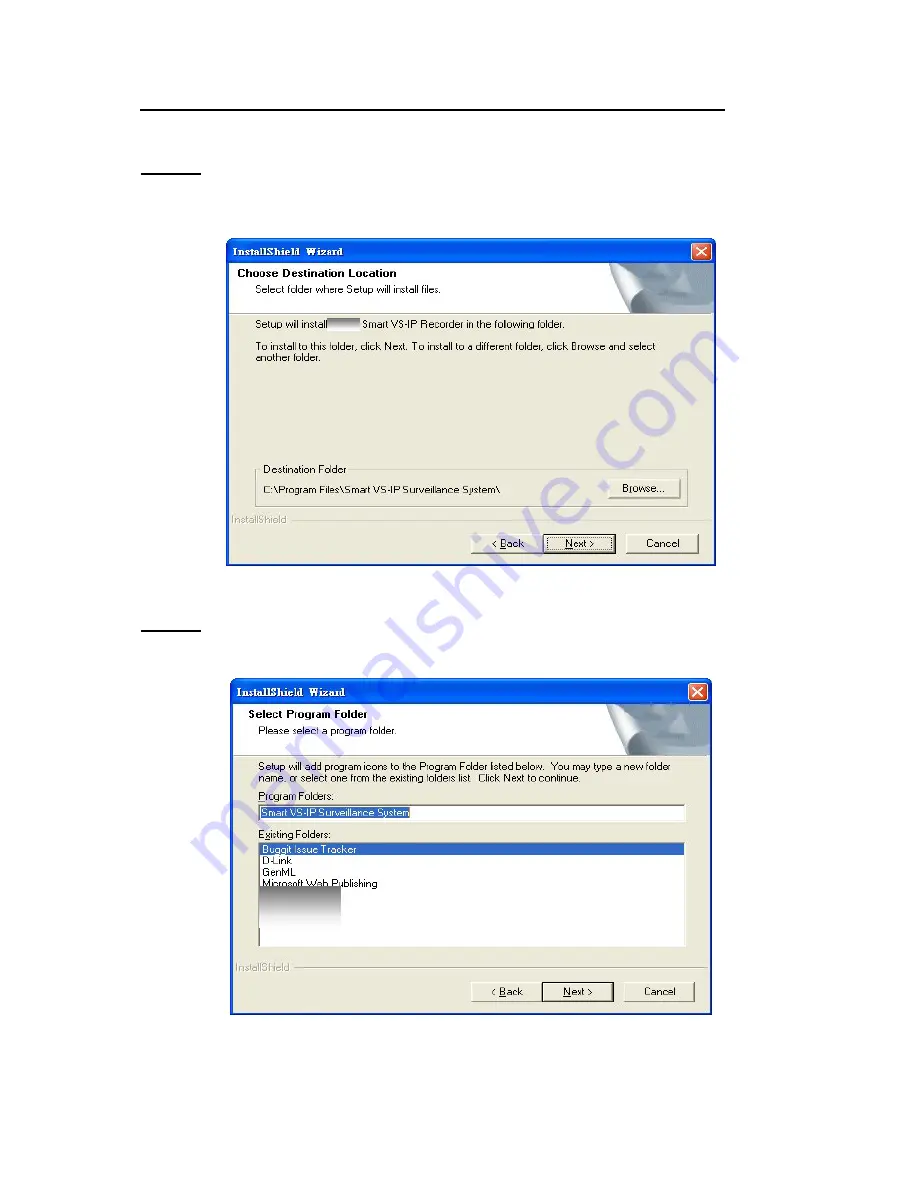
STEP 6:

 Select the installation directory for this application software and click on “Next”, as 

shown in Figure 1-6. You can also change the installation directory from the Default directory by 
clicking on “Browse…” 

Figure 1-6 Destination Location for Installation 

STEP 7:

 Select a program folder to install the application software into and then click on “Next”, 

as shown in Figure 1-7. 

Figure 1-7 Select Program Folder 

Summary of Contents for Net-Vision HNC700PT

Page 1: ......

Page 2: ...unctionalities 3 14 3 3 Logging In 3 16 3 3 1 The Root Privilege 3 16 3 3 2 The General User Privilege 3 16 3 4 Camera Configurations 3 17 3 4 1 The Layout of the Configuration 3 17 3 4 2 Local Settin...

Page 3: ...le in Continuous mode 4 55 4 4 Secondary Schedule 4 55 4 4 1 Schedule modes 4 55 Chapter 5 Playback 5 56 5 1 Features of Playback 5 56 5 2 Logging In 5 57 5 3 Layout 5 58 5 3 1 Main Areas 5 58 5 3 2 I...

Page 4: ...DRAM 256 MB SDRAM Hard disk 40 GB Display Chip nVidia GeForce series with 32 MB Display memory ATI Radeon series with 32 MB Display memory Table 1 1 Recommended System Hardware Requirements The follow...

Page 5: ...CD ROM drive and installation should start automatically If installation does not start click on Start on the lower left corner of your screen and open My Computer and double click on the CD ROM icon...

Page 6: ...gure 1 2 Welcome page for the Management Control Software STEP 3 If you click on Next and Figure 1 3 appears it means you have installed a previous version of the recording software the previous versi...

Page 7: ...his window prompts you to enter a username company name Click on Next to continue Figure 1 4 User information for Management Control Software STEP 5 Set up the administrator s password by entering a p...

Page 8: ...on Next as shown in Figure 1 6 You can also change the installation directory from the Default directory by clicking on Browse Figure 1 6 Destination Location for Installation STEP 7 Select a program...

Page 9: ...ormation shown in Figure 1 8 click on Next to start file movement and registries update Figure 1 8 Check Setup Information STEP 9 Click on Finish as shown in Figure 1 9 to finish installation This com...

Page 10: ...non encrypted data in the path Start Settings control Panel Internet Options Security Custom Level Setting You can also find the path from the IE browser as it is depicted in the following You can fol...

Page 11: ...uncher icon in the system tray the program will pop up a username password dialog This happens if this is a first time menu pop up or when Launcher was locked If the user fails to pass the authenticat...

Page 12: ...terface for Launcher Figure 2 3 Popup Menu The main user interface for Launcher is an icon on the system tray The popup menu is diplayed by clicking on the right or left buttons on the mouse The menu...

Page 13: ...s to run Launcher right after Windows boot up The state could be either on or off 4 Monitor This starts up the Monitor If the Monitor is already running move the focus to it 5 Playback This starts up...

Page 14: ...ul and convenient to use 9 Simultaneous real time monitoring and audio and video recording 9 High quality video up to full screen display 9 High compression ratio 9 Maximum support of 16 cameras with...

Page 15: ...tion full screen display lock stop alert and configuration menu for camera configurations global settings scheduler settings video audio database backup and the user information of this application so...

Page 16: ...ge for available storage size of the recorded video database 9 Common control area This area includes volume controller manual recording video printing and snapshot as well as a trash can to remove an...

Page 17: ...cal settings However this root privilege is not the same as that of the root privilege of the Video Server Network Camera series product You can change the settings of each selected Video Server Netwo...

Page 18: ...ow will pop up to warn you that all recording processes will be stopped 3 4 1 The Layout of the Configuration In this section we discuss the local settings of the connection and the functional configu...

Page 19: ...to the camera list Click on the Insert button an Insert New Channel dialog will pop up as shown in Figure 3 5 Specify the IP address port and root password of the remote Video Server Network Camera s...

Page 20: ...as shown in Figure 3 6 Figure 3 5 Insert New Channel Dialog Delete This removes the selected Video Server Network Camera series product from the camera list Figure 3 6 Adding a camera to the list IP a...

Page 21: ...history list is shown in Figure 3 7 Figure 3 7 Popup historical camera list 3 4 3 Alert Settings and Recording Settings Figure 3 8 Alert Settings and Recording Settings Alert Settings These settings...

Page 22: ...If you want to specify your own location name specify it in this field Otherwise leave this field with the default value Default You will get a default location name which concatenates the string in t...

Page 23: ...nges for all camera configurations will be saved and validated immediately in this IP surveillance system NOTE If you try to change the remote settings of any Video Server Network Camera series produc...

Page 24: ...for all the connected servers These include the video database directory the usage of the hard disk and options for video display Figure 3 10 Global Settings You can activate the global setting windo...

Page 25: ...n bmp format from channels as shown in Figure 3 11 9 Recording directory This is the directory for storing the recorded video data from remote channels 9 Scheduler directory This is the directory for...

Page 26: ...ton the button with black right arrow Modulation Mode You must select the input signal format NTSC or PAL to display the original resolution of video stream from the remote Video Server Network Camera...

Page 27: ...n the lower side the status includes Connection time and Recording time As shown in Figure 3 13 all can be enabled or disabled individually The Apply to full screen mode can also be turned on Once it...

Page 28: ...time of the last backup which indicates the time you last backed up to the dedicated media No Data means that there is no video data recorded for this channel All Backup means all the data in this lo...

Page 29: ...Chapter 2 Monitor 3 28 Figure 3 14 Account to Access Network Drive settings...

Page 30: ...ou can then click drag and drop the camera to the video area to monitor the remote video and apply other features if your privileges allow There is a unique light signal associated with each channel n...

Page 31: ...es product the light corresponding to the channel will blink if a motion event is detected Figure 3 15 Channel Area If you do not want to monitor one video you can click drag and drop the video in the...

Page 32: ...Move the mouse cursor to the channel number as shown in Figure 3 16 Figure 3 16 Mouse Cursor on the Channel Number Step 2 Press and hold down the left mouse button and drag the mouse cursor to the dis...

Page 33: ...Let us assume the video of Channel 1 is shown at display Frame X and the video of Channel 2 is shown at display Frame Y The channels associated with the dedicated display frames will be switched when...

Page 34: ...isplay frame associated with the channel you want to close Step 2 The cursor will turn into a hand shaped icon when it is moved to the display frame Press and hold with the left mouse button Step 3 Mo...

Page 35: ...n the Monitor tool You can select one of them by clicking on the left mouse button over the layout icon you want In each layout you can select drag and drop the channel number to any display frame in...

Page 36: ...out the Page up and Page down buttons will be shown in the bottom left corner of the video area You can use these two buttons to switch the pages as shown in Figure 3 22 Use the Page Up and Page Down...

Page 37: ...the dedicated channel in the video area You will see the size of the display frame is the same as the one camera layout Clicking on the Back button in the upper left corner of the video area will swi...

Page 38: ...Management Control Software User s Manual 3 37 Figure 3 23 Single View Mode When in Multi camera Layout Back to previous layout...

Page 39: ...control DI DO Digital Input Digital Output control and Alert Message receiver 3 6 3 1 PTZ Control The PTZ Pan Tilt Zoom tool is shown in Figure 3 25 in the bottom left corner If the remote Visual Ser...

Page 40: ...us of the DI Digital Input of the channel You can click on the Switch button to change the HI LOW state of the DO Digital Output These features allow you to monitor the remote sensor input from DI and...

Page 41: ...ed with the selected channel is in low level 3 6 3 3 Alert Message Figure 3 27 Alert Message If you select the check box for Enable Motion Detect or Enable Digital Input in the path Configuration Menu...

Page 42: ...backup settings From the backed up video data in the media you can duplicate the backup data to any removable device such as CD ROM ZIP disk DVD RAM or tape manually After backup settings have been c...

Page 43: ...ous functions represented by small icons in this application software as shown in Figure 3 30 These functions can be applied regardless of which is the currently focused channel These functions are ea...

Page 44: ...de the main window will be hidden and the lock dialog will appear To return to the main window you need to re enter the root s password Stop Alert Sound Whenever an alert is triggered an alarm will so...

Page 45: ...button to adjust the audio volume when monitoring provided the camera supports audio Record By clicking on this button you can manually activate video recording on the selected channel Stop record Th...

Page 46: ...el in current layout will be removed You can apply Volume Record Stop record Printer and Snapshot to several cameras simultaneously See Section 3 6 8 3 6 8 Multiple Focus Some functions can be applied...

Page 47: ...time shows the time when user logged in 9 Status message bar shows messages on some background operations such as repairing database or locations 9 Software name shows the software name of this appli...

Page 48: ...ideo Server Network Camera series product With both the graphic user interface and time period selection options you can easily schedule each channel The main features of the Scheduling tool are depic...

Page 49: ...s shown in Figure 4 1 there must be at least one camera on the camera list Otherwise the Scheduling tool cannot be invoked You will need to specify the database directory of the schedule schemes and t...

Page 50: ...erview of the Scheduling Tool The layout is roughly divided into 4 parts The first part of the Scheduling tool is the channel selection area It provides the IP addresses and location information of th...

Page 51: ...nel When you click on the row to select the channel the scheduling tool will load the dedicated schedule scheme associated with the selected channel automatically If the remote Video Server Network Ca...

Page 52: ...sed for undoing all plotting markers for this schedule scheme from the last save Clear This button is used for clearing all plotting markers in the current editing schedule scheme of the selected chan...

Page 53: ...coding Time Figure 4 6 One click on Week Time line The corresponding changes for the markers on the week time line will be automatically added to the hour time line as shown in Figure 4 6 You can also...

Page 54: ...nd ending time with them NOTE Normally the time set in Begin time must be earlier than that in End time But if this is not the case it means the time is over two days 4 3 2 2 Add and Erase Buttons Aft...

Page 55: ...e refer to Section 4 3 3 1 and Section 4 3 3 2 for more information Figure 4 10 Schedule Mode Selector 4 3 3 1 Motion detection Figure 4 11 Motion Detection Selector Figure 4 11 shows the window selec...

Page 56: ...you have selected the Continuous mode then it will record continuously according to the schedule set up by the user 4 4 Secondary Schedule Secondary schedule is the time that is outside the Primary s...

Page 57: ...nts preview There are several main tools consisting of special features in this Playback tool These tools are depicted as follow Powerful play control tools Play Stop Pause Step forward Fast play from...

Page 58: ...cellaneous tools Location selector Alert window selector 5 2 Logging In The authentication mechanism is implemented in Launcher If the user has passed authentication in Launcher Playback can be invoke...

Page 59: ...a There are also three visual indicators of the controls Area Selection Indictor Frame Selection Indictor and Pull Bar These features provide for powerful search for specific video recorded in the sur...

Page 60: ...Control Software User s Manual 5 59 Figure 5 2 Display By Time Normal Display Mode Figure 5 3 Display By Events Event Display Mode Display adjustment tool Playback method Frame Selection Indicator Pa...

Page 61: ...s 5 3 1 4 Status Area The Status Area is located at the bottom of the main window It shows all program status information including display mode display size display speed exporting file format and ex...

Page 62: ...om that point on If the replay is paused the display area will show the point you have selected Note that Pull Bar will only function under normal display mode 5 4 Settings Click on the Settings butto...

Page 63: ...be stored in a sub directory under the directory you have chosen here Figure 5 5 Settings Dialog AVI Compression Mode We use only 24 bits color depth to export the AVI file in this mode In the AVI co...

Page 64: ...e Control Panel Position This provides a convenient way to change the position of the control area either to to the left or right side of the main window according to your preference 5 5 Normal Single...

Page 65: ...hown in Figure 5 6 5 5 1 Histogram Area Figure 5 7 Histogram Area in Normal Display Mode The Histogram Area in the Normal display single frame mode only indicates the events occurred time and the perc...

Page 66: ...changed the playback method selector to Events Preview This can help you to identify the objects that triggered the events not only by the time information and the alert percentage in the histogram ar...

Page 67: ...the area selection indicator to the Histogram Area You can then mark a color inverted region over it by holding down the left mouse button and drag the cursor to the desired area as shown in Figure 5...

Page 68: ...t page closest to the point you have selected The dark regions means there is no video sequence existed in these intervals If you click on these regions a warning dialog will pop up 5 6 2 Histogram Le...

Page 69: ...od Selector and Alert Area Selector Figure 5 11 Selector Tools 5 7 1 1 Location Selector The Location Selector lets you select the camera you want to view from refer to Figure 5 11 The location inform...

Page 70: ...to the previously correct start and end times and a warning message will be shown 5 7 1 3 Playback Method Selector Full Range If you select this method the database will be displayed from the beginnin...

Page 71: ...rol For Play Control we used a jog dial as shown in Figure 5 13 to make it easier to control video sequence display Except for the Play button all other buttons can control the displaying frame in the...

Page 72: ...16 slow forward play This function provides you with more flexibility in browsing through the surveillance database If you want to change the playing speed you only need to move the speed indicator T...

Page 73: ...to 0 5 1 5 7 3 3 Full Screen When you click on the Full Screen button the video sequence will be enlarged to fill up the entire screen instantly You can double click on the mouse button in any area on...

Page 74: ...ess the start time or end time exceeds the location time boundary The scale of the Pull Bars and Histogram Area will also be changed The Period Selector will show the new start and end time And the Di...

Page 75: ...ake the program export a bitmap file In the Normal display mode the exporting bitmap is the image shown in the display area In the Preview mode it is the image that you selected through the frame sele...

Page 76: ...e away from your computer for security concerns we suggest you lock the Playback program You can simply click on the Lock Window button to lock the main window Once this is invoked the main window wil...

Page 77: ...ck again by clicking on the playback window on the task bar or choose Playback from the Launcher 5 7 6 4 Exit The Playback program will close as you click on the Exit button If the AVI exporting proce...

Reviews: