65
1018856
08/2018 V04
Brake voltage U
Br
[VDC]
Terminal voltage of the holding brake.
Continuous stall current I
0
[A
rms
]
Effective value of the motor phase current to produce the stall torque.
Continuous stall torque T
0
[Nm]
Allowable actuator stall torque.
Demagnetisation current I
E
[A
rms
]
Current at which rotor magnets start to demagnetise.
Dynamic axial load F
A dyn (max)
[N]
With the bearing rotating, this is the maximum allowable axial load with no additional radial forces or tilting moments
applied.
Dynamic load rating C [N]
Maximum dynamic load that can be absorbed by the output bearing before permanent damage may occur.
Dynamic radial load F
R dyn (max)
[N]
With the bearing rotating, this is the maximum allowable radial load with no additional axial forces or tilting moments
applied.
Dynamic tilting moment M
dyn (max)
[Nm]
With the bearing rotating, this is the maximum allowable tilting moment with no additional axial forces or radial forces
applied. This value is not based on the equation for lifetime calculation of the output bearing but on the maximum allowable
deflection of the Harmonic Drive® Component Set. This value must not be exceeded even if the lifetime calculation of the
bearing permits higher values.
Electrical time constant
τ
e
[s]
The electrical time constant is the time required for the current to reach 63 % of its final value.
Hollow shaft diameter d
H
[mm]
Free inner diameter of the axial hollow shaft.
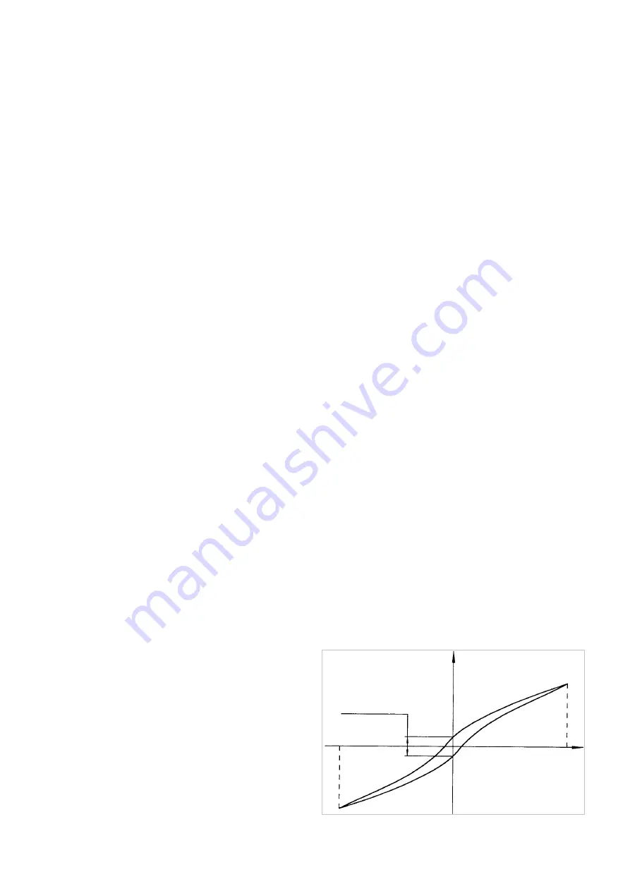
Hysteresis loss (Harmonic Drive® Gears)
When a torque is applied to the output of a Harmonic Drive®
Gear with the input locked, the torque-torsion relationship
measured at the output typically follows, starting from point
0, the successive points the hysteresis curve A-B-A'-B'-A
(see figure). The value of the displacement B-B' is defined as
the hysteresis loss.
T
N
= Rated output torque
φ
= Output rotation angle
-T
N
0
A‘
B
B‘
Hysteresis loss
Torsion
φ
A
Torque T + T
N


