background image

14

Martin Professional™ VC-Feeder user manual

P3™ system connections

In a Martin P3™ video display system, you supply the VC-Feeder with 
combined P3 video data and 48 VDC power from a suitable Martin P3 
power supply/data relay device such as the Martin P3 PowerPort 1500™.

Warning! Check the maximum current rating of each P3 power 
supply/data relay device output and make sure that the total current 
draw of all the devices connected to that output will not exceed 
either this maximum current rating or 7.5 A, whichever is lower.

The P3 PowerPort 1500 can safely supply 7.5 A at each of its four 
P3/48 VDC outputs.

To connect the VC-Feeder to P3 data and DC power:

1. Check that the system is isolated from AC mains power.

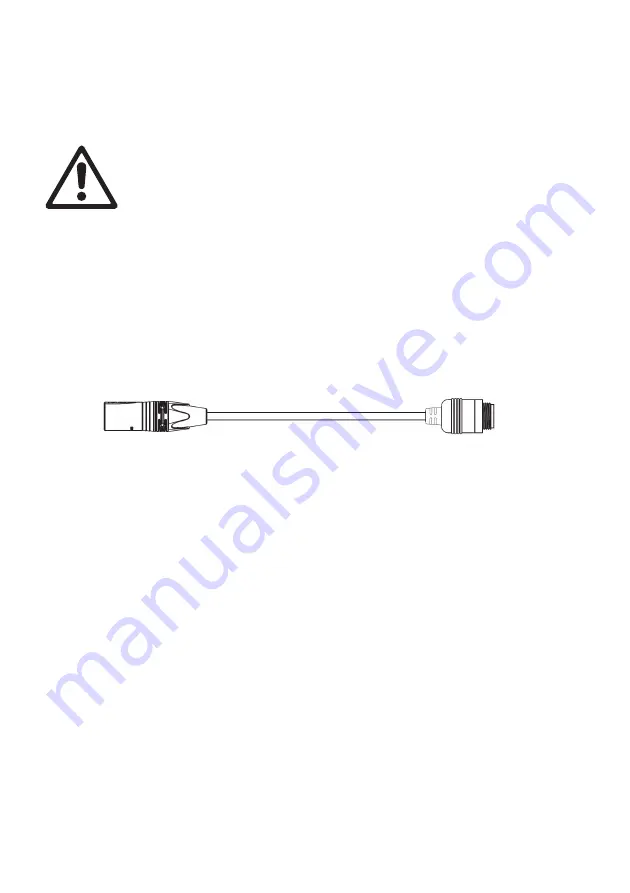
2. See Figure 4. Connect a Martin VC-Feeder Input Adapter Cable to a 4-

pin female XLR output on a suitable Martin P3 power supply/data relay 
device such as the P3 PowerPort 1500. 

3. Connect the VC-Feeder Input Adapter Cable to the VC-Feeder IN 

connector. If necessary, add extension cables (see ”Hybrid extension 
cables” 
on page 27) between the Input Adapter Cable and the VC-
Feeder IN connector.

DMX system connections

In a DMX-controlled system, you supply the VC-Feeder with DMX/RDM 
data from a DMX/RDM controller and 48 VDC power from an external 
PSU. You can use the Martin Tripix Power IP66™ external PSU or a 
generic external PSU (the Mean Well SP-480 48, for example).

The cables required are different depending on which type of PSU you 
use. The two different types of installation are covered in the next two 
sections.

Figure 4: Martin™ Hybrid Input Adapter Cable, P/N 11840165

From power

Power and data

to VC-Feeder IN

and data source

connector

4-pin male XLR

IP65 VC-Feeder connector

Summary of Contents for Martin VC-Feeder

Page 1: ...VC Feeder User Manual...

Page 2: ...e direct or indirect loss consequential or economic loss or any other loss occasioned by the use of inability to use or reliance on the information contained in this document The Martin logo the Marti...

Page 3: ...system connections 13 Throughput connections 17 Output connections 17 Throughput to other device types 18 Setup 19 Setting up for P3 video display 19 Setting up for DMX control 19 Operation 21 Ambien...

Page 4: ...eep this manual for future reference Manuals are supplied with devices and also available for download from www martin com Warning The VC Feeder is not for household use It presents risks of severe in...

Page 5: ...A limit If the device used to supply the chain with DC power has a maximum current rating that is less than 7 5 A it is the device s maximum current rating that determines the maximum current for the...

Page 6: ...ution equipment and cables are in perfect condition rated for the current requirements of all connected devices and of suitable type for the location including water pollution temperature and UV resis...

Page 7: ...l In an overhead installation or where the VC Feeder may cause injury if it falls block access below the work area and work from a stable platform whenever installing servicing or moving the VC Feeder...

Page 8: ...possible system layouts when using the VC Feeder with Martin video display products see the user documentation for those products Martin user documentation is supplied with products and available for...

Page 9: ...data output OUT connector Hybrid 48 VDC data throughput THRU connector Hybrid 48 VDC data input IN connector Rigging clamp attachment point Surface mount attachment point Surface mount attachment poin...

Page 10: ...re 1 on page 9 To fasten to a surface 1 Check that the surface is flat and stable and that the surface and all installation fasteners can support at least ten times the weight of all devices and hardw...

Page 11: ...ee Figure 1 on page 9 with a minimum grade 8 8 steel M12 bolt and lock nut 3 Block access under the work area Working from a stable platform fasten the product to the truss with the rigging clamp 4 In...

Page 12: ...to other devices using its throughput connector respect the maximum limits given in display device user manuals for the number of devices that can be linked in a chain and maximum permitted cable leng...

Page 13: ...nnector that accepts 48 VDC power and data Extension cables If the VC Feeder is not close to the power and data source you will need to extend the input cable To do this insert a Martin hybrid extensi...

Page 14: ...VC Feeder Input Adapter Cable to a 4 pin female XLR output on a suitable Martin P3 power supply data relay device such as the P3 PowerPort 1500 3 Connect the VC Feeder Input Adapter Cable to the VC F...

Page 15: ...rtin Hybrid Lead in Cable Tripix Power IP66 P N 11840195 to a DMX link from a DMX RDM controller and to the DC output of a Martin Tripix Power IP66 3 Connect the Hybrid Lead in Cable Tripix Power IP66...

Page 16: ...IP65 extension cable see Extension cables on page 13 between the Hybrid Lead in Cable and the VC Feeder IN connector 3 Connect the Hybrid Lead in Cable to the DMX data output of a DMX RDM controller...

Page 17: ...in If you want to install VC Feeders further apart than their THRU and IN connector cable tails allow insert a Martin IP65 extension cable see Hybrid extension cables on page 27 to extend the link bet...

Page 18: ...ply P3 or DMX data to other types of Martin display device Drawing off power and data Warning If you draw off DC power at the end of a chain of VC Feeders check that any additional devices will not ex...

Page 19: ...in a DMX universe The DMX address also known as the control address or start channel is the first of these channels Each group of devices uses this channel and the channels immediately above it to re...

Page 20: ...box See Figure 7 Opening the RDM View window in M PC and clicking on the Scan button arrowed bottom left gives a list of the RDM compliant devices on the data link in this example one string each of...

Page 21: ...o each VC Feeder by sending a video data signal from a Martin P3 system controller over the data link Displaying video on a VC installation is managed from the P3 system controller See the P3 controll...

Page 22: ...ndication Action required Blue Constant Busy e g booting up or writing to flash memory Wait a moment for normal operation to be resumed Red Constant Error The VC Feeder has encountered a fatal error a...

Page 23: ...short press Display the following test patterns on all the video display products that are correctly connected one short press scrolls to next pattern Calibrated white Full red Full green Full blue Ve...

Page 24: ...tion the user can carry out on the VC Feeder is occasional cleaning and uploading software if this should ever be necessary Cleaning Warning Do not immerse the VC Feeder or expose it to high pressure...

Page 25: ...correct VC Feeder setup Check that VC Feeder is correctly addressed and set up using the P3 controller or via RDM Check number of control channels required by display devices three channels for RGB fo...

Page 26: ...prietary P3 video data protocol Firmware update Via P3 System Controller Control User Interface Device status Multicolor status LED Device test and reset Pushbutton to call up local test patterns and...

Page 27: ...anadian EMC ICES 003 Class A Australia NZ C Tick N4241 Accessories Input cables Hybrid Input Adapter Cable 4 pin male XLR to 6 pin female IP65 0 25 m P N 11840165 Hybrid Input Adapter Cable 5 pin male...

Page 28: ...pitch 64 pcs 2 m lead in P N 90357120 Martin VC Dot 4 CW 200 mm pitch 64 pcs 2 m lead in P N 90357110 Martin VC Dot 9 RGB 400 mm pitch 36 pcs 2 m lead in P N 90357140 Martin VC Dot 9 WW 400 mm pitch...

Page 29: ...CC Compliance This device complies with Part 15 of the FCC Rules Operation is subject to the following two conditions 1 This device may not cause harmful interference and 2 this device must accept any...

Page 30: ......

Page 31: ......

Page 32: ...www martin com Olof Palmes All 18 8200 Aarhus N Denmark Tel 45 8740 0000 Fax 45 8740 0010...

Reviews: