


Page 8
DCP-555 Installation Guide
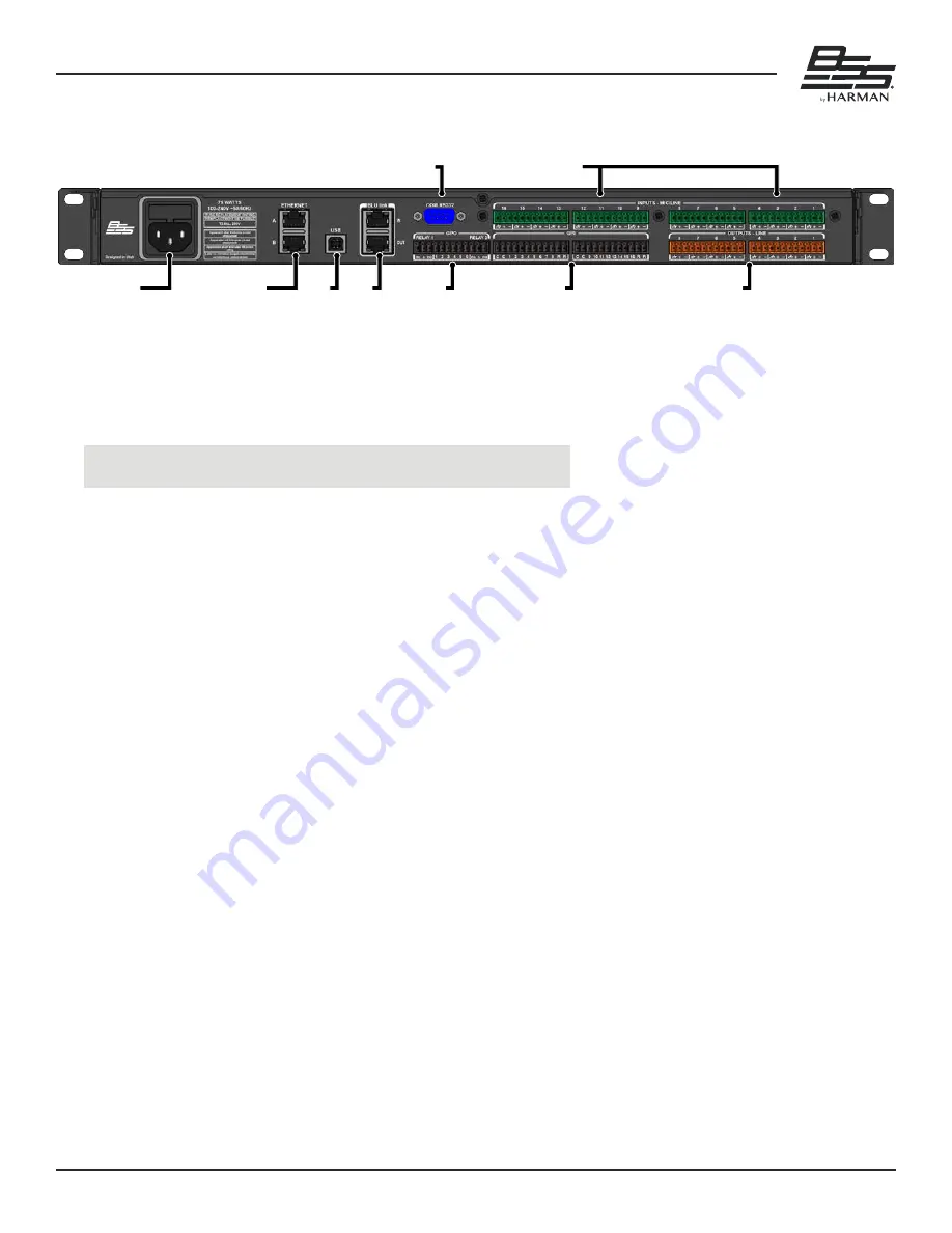
Rear Panel Overview
Rear Panel Overview
Ethernet B Status
Ethernet Port B
Gateway:10.34.6.1
Link:Connected
IP: 10.34.6.87
DHCP: ON
MAC:74:FE:48:26:F0:86
SUBNET: 255.255.254.0
Eth A
<
VoIP 1 <
Ethernet B Status
Ethernet Port B
Gateway:10.34.6.1
Link:Connected
IP: 10.34.6.87
DHCP: ON
MAC:74:FE:48:26:F0:86
SUBNET: 255.255.254.0
Eth A
<
VoIP 1 <
1
2
3
4
1
2
3 4
6
7
9
5
8
1. AC Mains Power Inlet
Connect the included IEC cable to this AC power inlet� The DCP-555 includes a universal power supply that
can operate from 100–240V, 50/60Hz� The fuse is housed in a user-accessable compartment above the AC
power inlet�
WARNING! Replace with same type fuse only (T2�5AL, 250V)�
2. Ethernet Ports
The DCP-555 has two Ethernet ports: Port A and Port B� Port A carries the AES67 traffic and Port B
carries the VoIP traffic� Port A and Port B carry the control data traffic for communication with the
DCP-555 control application and 3rd party control devices, so either can be used for control�
3. USB Port
Connect a computer to this port to use the DCP-555 as a USB audio interface with a room PC or AMX
Acendo Core for web conferencing� This port supports 2x2 audio channels at 48kHz� See
4. BLU Link Ports
BLU link is a proprietary point-to-point digital audio bus that can be used to expand the DCP-555's audio
I/O capabilites by interfacing with other BLU link-equipped HARMAN devices� The DCP-555 supports 28x32
BLU link channels at 48kHz� See
5. RS232 Port
The serial port allows 3rd party control equipment to control and monitor the DCP-555� See
for more information�
6. GPO Port
This General Purpose Output port can be used to control external LEDs and devices� See
for more information�
7. GPI Ports
These General Purpose Input ports can be used to control DCP-555 mutes and volume� See


