background image

Page 20

DCP-555 Installation Guide

Using 3rd Party Control

Using 3rd Party Control

The DCP-555 can be controlled by a 3rd party device via Ethernet or RS232� For more information, download 
the DCP-555 Control API Guide from https://bssaudio�com/en/products/dcp-555#documentation�

Performing the Factory Reset

The Factory Reset procedure can be used to reset all parameters within the DCP-555 back to their factory 
default state�

WARNING! Performing the Factory Reset will erase all user-configured settings� This process is irreversible� 
It is recommended to back up settings before performing this procedure�

To perform the Factory Reset:

1�  Power off the DCP-555�
2�  Apply power to the unit then immediately press and hold the 

ENCODER

� Keep the 

ENCODER

 pressed until 

the Factory Reset prompt appears on the front-panel LCD screen, then release it�

3�  Turn the 

ENCODER

 clockwise to confirm� 

4�  Press the 

ENCODER

 to start the Factory Reset procedure�  

NOTE: To abort the Factory Reset procedure, press the 

BACK

 button instead�

5�  Wait for the Factory Reset to complete�

Updating Firmware

To update the DCP-555 firmware:

1�  While connected to the Internet, launch the DCP-555 control app and sign in�
2�  Using the navigation menu icons on the left of the page, navigate to the "Device Settings" page� 
3�  Press the 

UpdateFirmware

 button then follow the on-screen instructions�

NOTE: If a network's firewall restricts access to the DCP-555 firmware download, it may be required to open 
port 80 in the network's firewall to allow for internet-based updates� See 

"PortAssignmentList"onpage

11

 for more information on the ports used by the DCP-555�

Summary of Contents for BSS DCP-555

Page 1: ...DCP 555 Digital Conferencing Processor Installation Guide ...

Page 2: ...ol Device Specifications 11 Port Assignment List 11 Connecting to the Network 11 Connecting to the Web Server App 12 Using BLU Link 12 Making BLU Link Connections 12 Fault Tolerance 12 BLU Link Mastership 13 BLU Link Port Status LEDs 14 Using the USB Port 15 Using the General Purpose Inputs GPI 16 Contact Closure 16 Volume Control via Potentiometer 17 Volume Control via AC V Wall Controller 17 Usi...

Page 3: ...ffers four bidirectional VoIP connections providing support for up to four rooms of audio conferencing connectivity without the need for separate IP phones in each room The DCP 555 also offers a range of onboard audio I O connection options including analog AES67 BLU link and USB And with GPIO RS232 and Ethernet built in the DCP 555 supports additional control via potentiometers contact closure an...

Page 4: ... Easily interface audio with other BLU link equipped HARMAN audio products such as BSS Soundweb London processors BSS BLU USB interfaces or Crown amplifiers USB Port 2x2 Audio Interface Use the DCP 555 as a USB audio interface with a room PC or AMX Acendo Core for web conferencing If additional USB connections are required expand the system with up to 4 BSS BLU USB interfaces sold separately 28x12...

Page 5: ... warranty_policy Included Items Quantity Item 1 DCP 555 Conferencing Processor 16 Audio Input Connectors 3 5mm 3 pin green Euroblock 8 Audio Output Connectors 3 5mm 3 pin orange Euroblock 3 GPIO Connectors 3 5mm 12 pin black Euroblock 2 Hardware Brackets for under table mounting 4 5 8 Wood Screws for under table mounting 4 Rubber Bumpons for table top use 1 Power Cord 1 Rack Mount Screw Kit 4x scr...

Page 6: ...ons near the bottom corners of the chassis to prevent the DCP 555 from sliding around Under Table Mounting Additional tools and supplies required Phillips screwdriver Torx T10 screwdriver optional To mount the DCP 555 under a table 1 For a cleaner look remove the rack ears using a Torx T10 screwdriver optional Note that it is recommeneded to re insert the screws to avoid losing them and to maintai...

Page 7: ...o the same network as the DCP 555 4 Open a browser on the control device and type the IP address from step 2 in to the address field The web server app should launch in the browser if both devices are connected to the same network 5 To log in enter administrator for the password Once logged in you can change the password by clicking the User icon in the upper right hand corner of the window 6 Load...

Page 8: ... IP 10 34 6 87 DHCP ON MAC 74 FE 48 26 F0 86 SUBNET 255 255 254 0 Eth A VoIP 1 1 2 3 4 1 2 3 4 6 7 9 5 8 1 Air Vents These vents provide air flow through the processor Do not obstruct these vents 2 LCD This liquid crystal display provides visual feedback when navigating the front panel menus 3 Back Button Pressing this button will navigate backwards in the front panel menu heirarchy 4 Encoder Turn...

Page 9: ...ol 3 USB Port Connect a computer to this port to use the DCP 555 as a USB audio interface with a room PC or AMX Acendo Core for web conferencing This port supports 2x2 audio channels at 48kHz See Using the USB Port on page 15 for more information 4 BLU Link Ports BLU link is a proprietary point to point digital audio bus that can be used to expand the DCP 555 s audio I O capabilites by interfacing...

Page 10: ...increments The maximum input level is 20dBu with an input gain setting of 0dB Phantom power 48VDC is provided for condenser type microphones and is software selectable per input channel 9 Line Outputs These 8 line level analog outputs have a maximum output level of 20dBu and support balanced or unbalanced connections Mute control is available for each output and can be controlled via the app or GP...

Page 11: ... The DCP 555 provides cable shielding back from the destination to eliminate ground loop problems This means that the shield connection on an input is grounded whereas the shield connection on an output is floating although connected via an internal network to ground for EMC compliance Balanced Wiring The convention for balanced wiring 2 core plus shield is shown below Unbalanced Wiring The conven...

Page 12: ...k apply power then wait for the DHCP server to assign the unit an IP address The IP address can be confirmed from the front panel by turning the ENCODER to navigate to the Ethernet A Status or Ethernet B Status screen depending on which Ethernet port the network cable is connected Ethernet B Status Ethernet Port B Gateway 10 34 6 1 Link Connected IP 10 34 6 87 DHCP ON MAC 74 FE 48 26 F0 86 SUBNET ...

Page 13: ...LU link OUT port of one device to the BLU link IN port of another device Additional devices should be connected in a daisy chain topology Redundancy can be provided by completing the loop and connecting the BLU link OUT port from the last device to the BLU link IN port of the first device The maximum cable length between devices cannot exceed 100m 328ft The BLU link audio bus supports a maximum of...

Page 14: ...and 254 Some BLU link devices have a fixed Master Priority setting while others are configurable The device with the highest Master Priority setting on the bus will be configured as the BLU link master If two BLU link devices have the same Master Priority setting then the device s MAC addresses are compared to determine which will be the master with the device with the higher MAC address winning I...

Page 15: ...ange LED Lit This indicates the device is slaved to the BLU link clock received from another device on the bus Green Green Off Off Both Orange LEDs Off This indicates the device is not receiving BLU link clock and will not pass audio This usually indicates the IN and OUT ports are swapped on the device an OUT port is connected to an OUT port and an IN port is connected to an IN port Try swapping t...

Page 16: ...er then select it as the sound input and output device in the computer If additional USB ports are required or the DCP 555 s USB port is not accessible due to installation location up to 4 BSS BLU USB interfaces can be connected via the BLU link ports Visit https bssaudio com en products blu usb for more information on the BLU USB NOTE To use the BLU USB with the DCP 555 the BLU USB must be set to...

Page 17: ...es for control of mutes or potentiometers for control of volume GPI connections are made using the included black 12 pin terminal block connectors HARMAN part number 32 1006 There are two common ground C pins to the left and two reference voltage R pins to the right that provide an output of 5VDC Contact Closure Connect a momentary switch for push to talk control or connect a latching switch for m...

Page 18: ... input and common to control volume linearly 47kΩ Logarithmic Potentiometer Volume Control via AC V Wall Controller For an easy to integrate and stylish solution connect a BSS Soundweb Contrio AC V Wall Controller for volume control Visit https bssaudio com en products ac v for more information on the AC V Wall Controller Level Ground Contrio AC V Wall Controller ...

Page 19: ...006 The GPO logic outputs can source 10mA at 5VDC or sink up to 50mA of current as an open collector output For higher current reed type relays you must use one of the GPO logic outputs to sink current using an external power supply LED Indication When sourcing from a logic output an LED connected between one output Anode A and common Cathode K will illuminate when the logic output is activated wi...

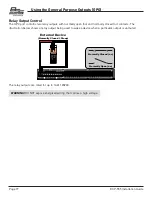
Page 20: ...rmally open no and normally closed nc contacts The illustration below shows a relay output being used to wake a device when a particular output is unmuted External Device Normally Closed Sleep Normally Closed nc Normally Open no The relay outputs are rated for up to 1A 120VAC WARNING DO NOT expose energized wiring that carries a high voltage ...

Page 21: ... and hold the ENCODER Keep the ENCODER pressed until the Factory Reset prompt appears on the front panel LCD screen then release it 3 Turn the ENCODER clockwise to confirm 4 Press the ENCODER to start the Factory Reset procedure NOTE To abort the Factory Reset procedure press the BACK button instead 5 Wait for the Factory Reset to complete Updating Firmware To update the DCP 555 firmware 1 While c...

Page 22: ...icon removable screw connectors Output Impedance 40Ω balanced 20Ω unbalanced Maximum Output Level 20dBu Frequency Response 20Hz 20kHz 1dB 1dB THD 0 5 20Hz 20kHz 0dBu output Dynamic Range 108dB typical 22Hz 22kHz unweighted 110dB typical 22Hz 22KHz A weighted Crosstalk 75dB D A Word Length 24 bit D A Latency 29 Fs 0 60 ms 48kHz CONTROL PORTS Number of Ports 16 inputs 6 outputs and 2 relay contact c...

Page 23: ...g Temperature Range 0º to 45º C 32º to 113º F PHYSICAL Rack Space 1U Dimensions H x W x D 1 7 x 19 x 13 43mm x 483mm x 330mm width includes rack mounts Weight 9 4 lbs 4 3 kg Specifications subject to change without notice BSS Audio incorporates high quality mechanical fans in some products All mechanical fans have a limited life expectancy We recommend annual inspection of fans for dust occlusion ...

Page 24: ...SS Audio is a registered trademark of HARMAN 2018 HARMAN All rights reserved Printed in USA DCP 555 Installation Guide PN 5093584 00 A Phone 844 776 4899 Website bssaudio com Support support bssaudio com ...

Reviews: