


SYSTEM SETUP
39
ENGLISH
System Setup
Delay
Due the different distances between the listening
position for the front channel speakers and the
surround speakers, the amount of time it takes
for sound to reach your ears from the front or
surround speakers is different. You may
compensate for this difference through the use of
the delay settings to adjust the timing for the
specific speaker placement and acoustic con-
ditions in your listening room or home theater.
Measure the distance from the listening position
to each of the individual loudspeakers. Once
done, select per loudspeaker the distance that is
closest to the one measured.
Output level adjustment
Output level adjustment is a key part of the
configuration process for any surround sound
product. It is particularly important for DVD-
Audio, as correct outputs will ensure that you
hear sound tracks with the proper directionality
and intensity.
NOTE:
Listeners are often confused about the
operation of the surround channels. While some
assume that sound should always be coming
from each speaker, most of the time there will be
little or no sound in the surround channels. This is
because they are only used when a movie direc-
tor or sound mixer specifically places sound there
to create ambiance, a special effect or to contin-
ue action from the front of the room to the rear.
When the output levels are properly set it is
normal for surround speakers to operate only
occasionally. Artificially increasing the volume to
the rear speakers may destroy the illusion of an
enveloping sound field that duplicates the way
you hear sound in a movie theater or concert
hall.
The default settings of the DVD player is 0dB for
all channels. In case you feel adjustments are
necessary in your setup, we advise you to copy
the settings currently in use with 5.1 surround
modes (for instance Dolby Prol Logic II) of your
AV receiver to the DVD player.
Video Settings
The Video Setting Submenu contains the
following settings. Follow the explanations in the
Instruction Line on the bottom of your screen to
change the settings.
Aspect Ratio:
This step selects the TV aspect
ratio, conventional screen shape (4:3) or
widescreen (16:9), according to your TV.
When the
HDMI Output
is used, the aspect
ratio will automatically be set appropriately for
the specific display. However, you may select an
alternate view.
Video Standard:
Sets the output video format
i.e. NTSC, PAL or SECAM, of the DVD player. If
you have a multi standard TV, we recommend the
AUTO setting for optimal picture quality.
Video Output:
Sets the video output type to
S-Video, Component or SCART. Scart will be used
for most TV’s. Component will be used for most
LCD, Plasma and projectors.
Scan Type:
This setting allows you to select
between progressive and interlaced scanning for
the
Component Video Outputs
to maxi-
mize the image resolution for the type of video
display in use. The output at the S-Video
and
Composite Video
outputs will always be
standard-rate video that is compatible with any
television set or video display. Two choices are
available:
Progressive:
Select this option if you have a
video display that is compatible with input
sources of 480P or greater. Displays labeled as
“HDTV Ready,” including virtually all large-screen
LCD and plasma displays, are compatible with
progressive scan.
Interlaced:
Select this option when you are
using an older video display that has Y/Pr/Pb
component inputs, but which is not capable of
displaying high scan rate, or “HD” signals.
NOTES:
1. The Scan Type may only be changed when the
Video Output setting has been set to
Component.
2. If you have connected the DVD 28 to a video
display that is not capable of displaying
progressive scan video using the Component
(Y/Pr/Pb)
Video Outputs
, and you have
inadvertently changed the Video Output
Setting to Component and the Scan Type
setting to Progressive, you may reset the scan
type to interlaced by pressing the
Progressive Scan/Interlaced Button
F
.
The display will blink, indicating that the scan
type has been reset to interlaced mode.
Scart Output:
Selects which kind of video
output signals will be routed over the scart.
RGB will be used for most TV’s and is therefore
recommended.
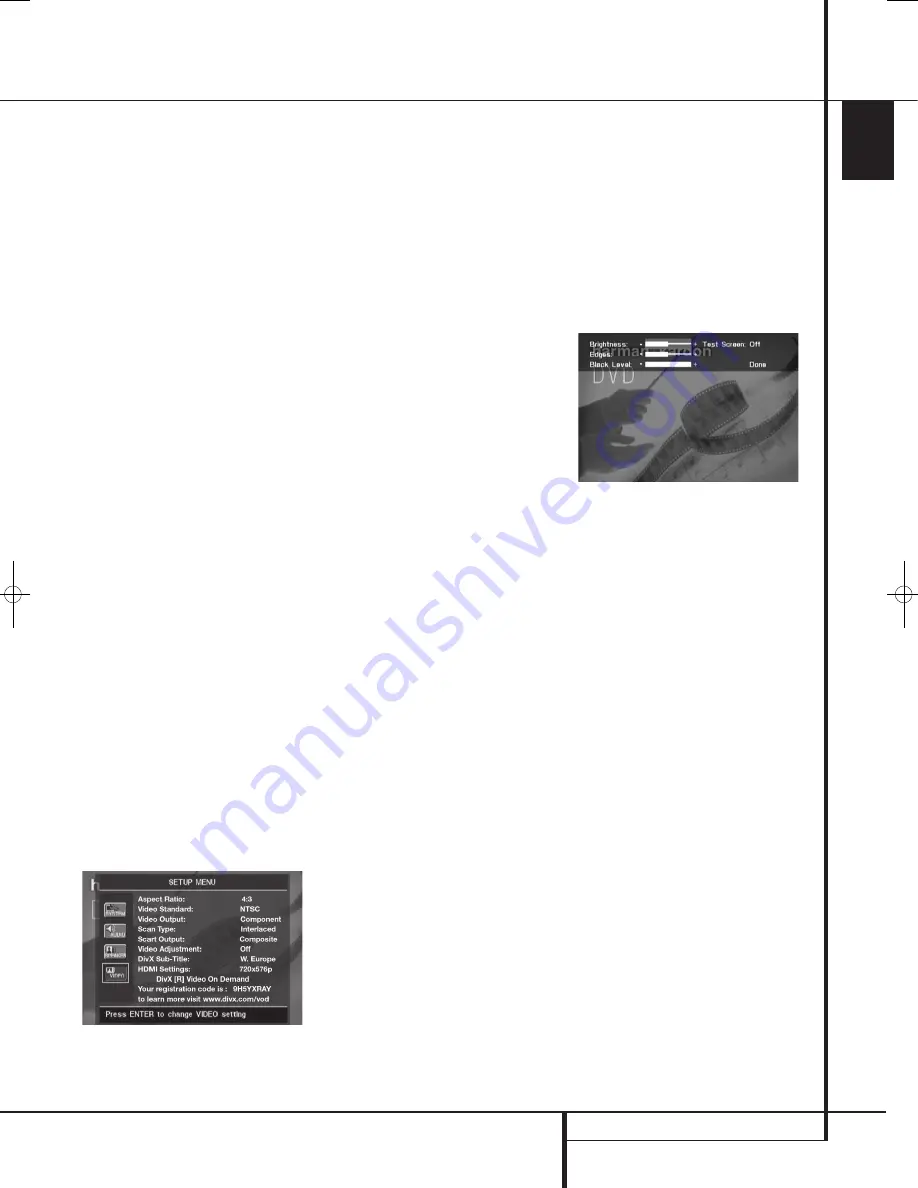
Video Adjustment:
The Video Adjustment
Submenu contains access to the Test Screen. First
adjust the video display device (TV) with the help
of the Test Screen. After that the output settings
of the player can be fine-tuned with the
Brightness, Sharpness and Black Level settings. In
order to change the settings, move the cursor to
the “+“ or “-“ icon on the same line as the set-
ting. Once one of the icons is highlighted, press-
ing OK will increase or decrease the value of the
setting, as will be shown in the bar behind the
setting. To exit the Video Adjustment Menu,
move the cursor to DONE, and press OK.
DivX Subtitle:
This setting selects the desired
subtitle language for DivX movies.
Below the menu items you will find your personal
DivX Video On Demand (VOD) code.
This code allows you to rent and purchase videos
using the DivX VOD service. For more infor-
mation, visit www.divx.com/vod. Follow the
instructions and download the video onto a disc
for playback on this unit. Note that all the
downloaded videos from DivX VOD can only be
played back on this unit.
Once the DivX icon is highlighted, press OK to
access your personal DivX VOD code.
HDMI Settings:
This setting displays the
characteristics of the video output signal at the
HDMI Output
. When the DVD 28 is
connected to a video display using the
HDMI
Output
, the display sends information to the
DVD 28 that indicates the highest video
resolution it is capable of handling, and the
DVD 28 automatically sets the video output to
match it. That resolution is displayed here. You
may use this setting to manually select a lower
video output resolution. Changes made here
remain active until the DVD 28 or the display is
turned off. When either is turned off, and then on
again, the DVD 28 will revert to the default
setting transmitted by the display. Make sure
your video display or other video switching
equipment (such as an HDMI-capable receiver) is
capable of handling the DVD 28’s HDMI output
signal.
38277_AVR138_DVD28_ENG 23/07/08 18:36 Side 39


