
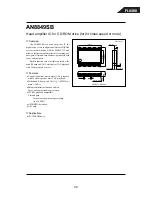
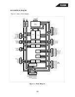


FL8380
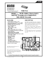
PCM1732
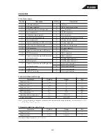
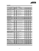
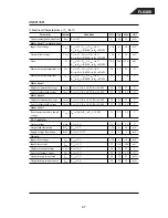
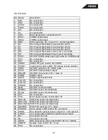
PIN
NAME
I/O
DESCRIPTION
1
LRCIN
IN
Left and Right Clock Input. This clock is equal to
the sampling rate, f
S
.
(1)
2
DIN
IN
Serial Audio Data Input
(1)
3
BCKIN
IN
Bit Clock Input for Serial Audio Data
(1)
4
CLKO
OUT
Buffered System Clock Output.
5
XTI
IN
Oscillator Input/External Clock Input
(2)
6
XTO
OUT
Oscillator Output
7
DGND
—
Digital Ground
8
V
DD
—
Digital Power +5V
9
HDCD
OUT
HDCD Encoded Data Detect
10
V
CC
2R
—
Analog Power +5V, Rch
11
AGND2R
—
Analog Ground, Rch
12
EXTR
—
Common Mode Voltage for Analog Output Amp,
Rch
13
V
OUT
R
OUT
Analog Voltage Output, Rch
14
AGND1
—
Analog Ground
15
V
CC
1
—
Analog Power +5V
16
V
OUT
L
OUT
Analog Voltage Output, Lch
17
EXTL
—
Common Mode Voltage for Analog Output Amp,
Lch
18
AGND2L
OUT
Analog Ground, Lch
19
V
CC
2L
—
Analog Power +5V, Lch
20
GAIN
OUT
External (analog) Gain Scaling
21
ZERO
OUT
Zero Data Flag
22
RST
IN
Reset. When this pin is LOW, the digital filter
and modulators are held in reset.
(3)
23
CS/IW0
IN
Chip Select/Input Format Selection. When this
pin is LOW, the Mode Control interface is en-
abled.
(4)
24
MODE
IN
Mode Control Select: H = Software; L =
Hardware
(3)
25
MUTE
IN
Mute Control
(3)
26
MD/FSS
IN
Mode Data/Sampling Rate Range Select
(3)
27
MC/DEM
IN
Mode Clock/De-Emphasis Select
(3)
28
ML/I
2
S
IN
Mode Latch/Input Format Select
(3)
NOTES: (1) Schmitt Trigger input. (2) CMOS logic level input. (3) Schmitt
Trigger input with pull-up resister. (4) Schmitt Trigger input with pull-down
resistor.
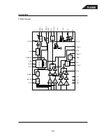
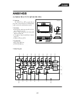
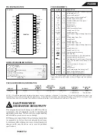
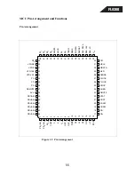
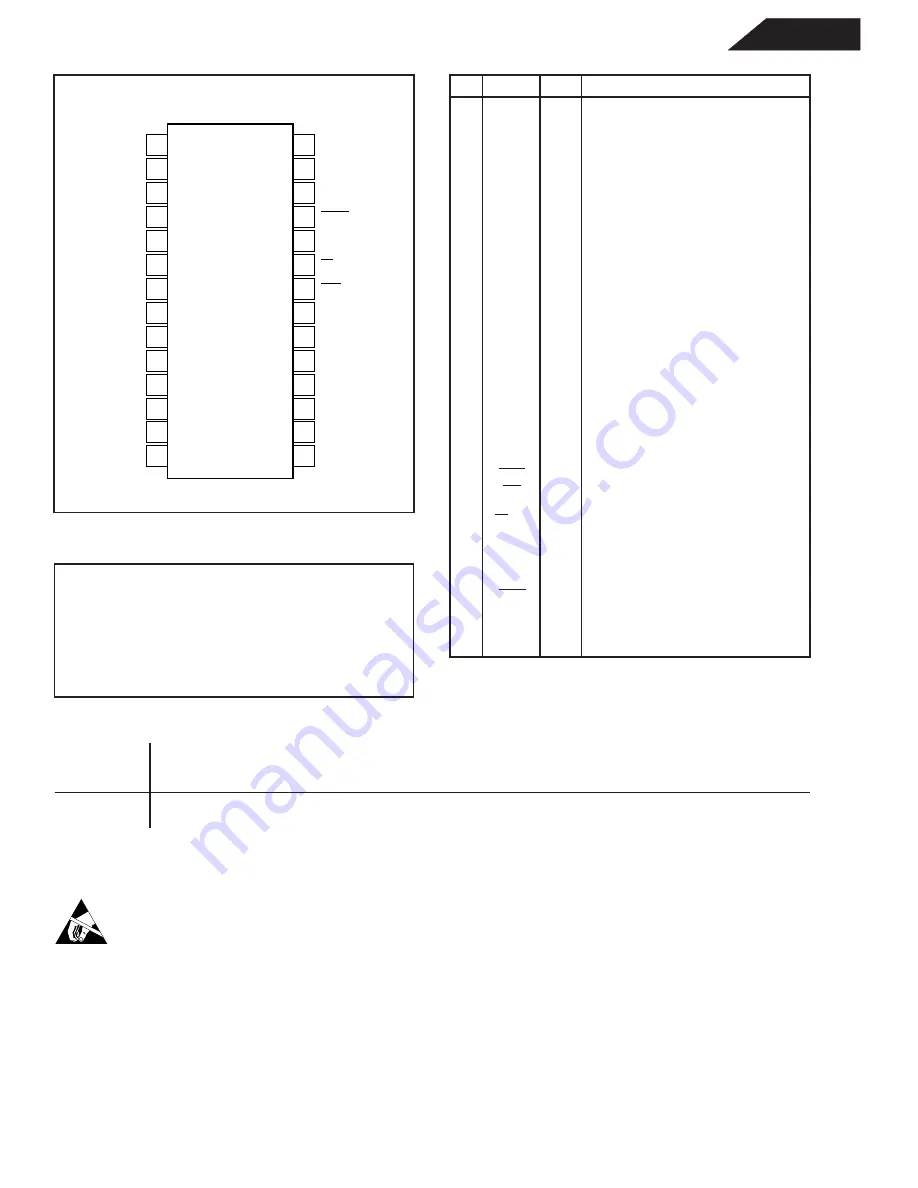
PIN ASSIGNMENTS
PIN CONFIGURATION
ELECTROSTATIC
DISCHARGE SENSITIVITY
This integrated circuit can be damaged by ESD. Burr-Brown
recommends that all integrated circuits be handled with
appropriate precautions. Failure to observe proper handling
and installation procedures can cause damage.
ESD damage can range from subtle performance degradation
to complete device failure. Precision integrated circuits may
be more susceptible to damage because very small parametric
changes could cause the device not to meet its published
specifications.
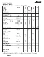
Power Supply Voltage ...................................................................... +6.5V
+V
CC
to +V
DD
Difference ...................................................................
±
0.1V
Input Logic Voltage .................................................. –0.3V to (V
DD
+ 0.3V)
Input Current (except power supply) ...............................................
±
10mA
Power Dissipation .......................................................................... 750mW
Operating Temperature Range ......................................... –25
°
C to +70
°
C
Storage Temperature ...................................................... –55
°
C to +125
°
C
Lead Temperature (soldering, 5s) ................................................. +260
°
C
(reflow, 10s) .................................................... +235
°
C
ABSOLUTE MAXIMUM RATINGS
LRCIN
DIN
BCKIN
CLKO
XTI
XTO
DGND
V
DD
HDCD
V
CC
2R
AGND2R
EXTR
V
OUT
R
AGND1
ML/I
2
S
MC/DEEM
MD/FSS
MUTE
MODE
CS/IWO
RST
ZERO
GAIN
V
CC
2L
AGND2L
EXTL
V
OUT
L
V
CC
1
1
2
3
4
5
6
7
8
9
10
11
12
13
14
28
27
26
25
24
23
22
21
20
19
18
17
16
15
PCM1732U
Top View
SO-28
PACKAGE
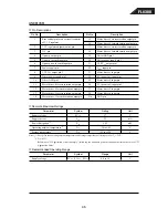
SPECIFIED
DRAWING
TEMPERATURE
PACKAGE
ORDERING
TRANSPORT
PRODUCT
PACKAGE
NUMBER
(1)
RANGE
MARKING
NUMBER
(2)
MEDIA
PCM1732U
SO-28
217
–25
°
C to +70
°
C
PCM1732U
PCM1732U
Rails
"
"
"
"
"
PCM1732U/1K
Tape and Reel
NOTES: (1) For detailed drawing and dimension table, please see end of data sheet, or Appendix C of Burr-Brown IC Data Book. (2) Models with a slash (/) are
available only in Tape and Reel in the quantities indicated (e.g., /1K indicates 1000 devices per reel). Ordering 1000 pieces of “PCM1732U/1K” will get a single
1000-piece Tape and Reel. For detailed Tape and Reel mechanical information, refer to Appendix B of Burr-Brown IC Data Book.
PACKAGE/ORDERING INFORMATION
52
Summary of Contents for FL 8380
Page 21: ...FL8380 ...
Page 22: ...FL8380 ...
Page 23: ...FL8380 ...
Page 24: ...FL8380 ...
Page 25: ...FL8380 ...
Page 27: ...FL8380 27 ...
Page 28: ...FL8380 28 ...
Page 29: ...FL8380 29 ...
Page 30: ...FL8380 30 ...
Page 31: ...FL8380 31 ...
Page 32: ...FL8380 32 ...
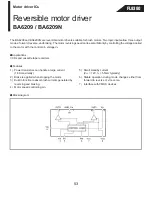
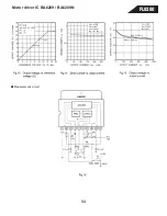
Page 54: ...Motor driver IC BA6209 BA6209N Measurement circuit FL8380 54 ...
Page 59: ...FL8380 59 ...
Page 60: ...FL8380 60 ...
Page 68: ...FL8380 68 ...
Page 69: ...FL8380 69 ...
Page 70: ...FL8380 70 ...
Page 71: ...FL8380 71 ...


