


CONFIGURING THE REMOTE 39
7. Once the punch-through is programmed, the
transport buttons of the second device named
will be used when those buttons are pressed
while the master device is in use.
Returning the Transport Control Settings to
Default Operation:
If you wish to remove the Transport Punch-Through so
that the transport commands are returned to the fac-
tory default setting, follow the steps shown above,
except that in Steps 4 and 5, select the same device
for both the
DEVICE IN USE
on the left side of the
bottom line and the
PUNCH-THROUGH
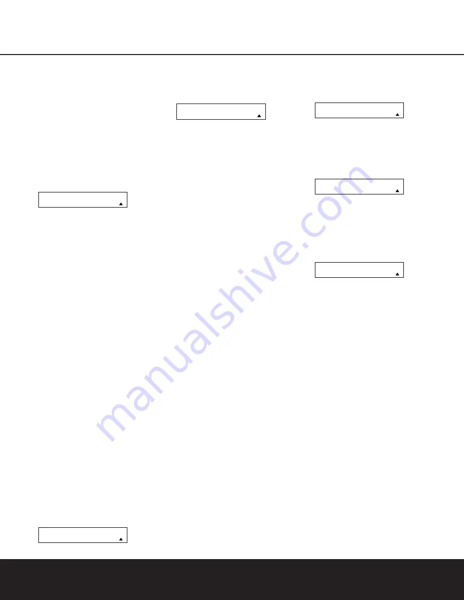
device. In
the example used, the display to return the remote to
default settings will appear as shown in Figure 63.
Figure 63
EzSet Configuration
Harman Kardon’s patented EzSet feature makes it
easier than ever to calibrate the output levels on your
new DPR for maximum playback accuracy. In addition
to automatically setting the levels, the DPR remote’s
LCD display allows the unit to be used as a direct
read-out SPL meter. Complete instructions for using
the EzSet features of the DPR remote are found on
pages 22 and 23 of this owner’s manual.
In most cases you will find it easier to access the
EzSet capabilities directly by pressing the
SPL Select
Button
and following the menu prompts as
detailed in pages 22 and 23. However, there is one
function of the remote that is only available through
the remote’s menu system being described in this
section.
To avoid having the calibration settings created with
EzSet changed accidentally, the remote allows you to
disable the
SPL Select Button
on the remote.
To de-activate the button, follow these steps:
1. Press and hold the
Program Button
O
for
about three seconds while the message shown
in Figure 15 appears in the remote’s
LCD
Information Display
2
. Release the button
when the red light under the
Set Button
F
appears.
2. The remote’s
MAIN MENU
message (Figure 16),
will appear in the LCD display and the
Set Button
F
will remain illuminated in red. Press the
⁄
/
¤
Navigation Buttons
n
until
SET
SPKR LEVELS
appears on the bottom line of
the LCD screen, as shown in Figure 64. Press the
Set Button
F
to enter the main EzSet menu
branch.
Figure 64
3. At the next menu screen (Figure 65) press the
⁄
/
¤
Navigation Buttons
n
once so that
EZSET DISABLE
appears in the lower line of
the LCD display.
Figure 65
4. Within five seconds, press the
Set Button
F
to
disable the
SPL Select Button
. Once the
Set Button
F
is pressed the word
EXITING
will flash four times in the lower line of the LCD
display and then it will return to normal operation.
Once these steps are completed, when the
SPL
Select Button
is pressed the remote will show
EZSET DISABLE
and it will not be activated.
To restore the EzSet feature to normal operation,
repeat the procedure outlined above, except that in
step #3 you should press the
⁄
/
¤
Navigation
Buttons
n
so that
EZSET ENABLE
appears in
the lower line of the LCD display. When that display
appears, press the
Set Button
F
and the EzSet
feature will be reactivated. You may then press the
Clear Button
9
to exit the remote’s menu system
and return to normal operation or press the
Set
Button
F
again to immediately use the EzSet
feature to calibrate the system as shown on pages
22 and 23.
Renaming
While the names given to the buttons and inputs on
the DPR represent recognizable categories of audio/
video products, system operation may be easier if the
displays shown in the remote’s LCD screen are cus-
tomized to reflect the specific characteristics of a play-
back source’s brand name or the new function given
to a specific button when one remote’s controls are
programmed into the DPR remote. The DPR remote
allows you to change the name of either a master
device or any button on the remote using the following
steps.
Renaming a Device
To rename a specific device/input source button, fol-
low these steps. For this example, we will show you
how to rename the Device/Input Selector normally
shown as “TV” to “HDTV TUNER.”
1. Press and hold the
Program Button
O
for
about three seconds while the message shown
in Figure 15 appears in the remote’s
LCD
Information Display
2
. Release the button
when the red light under the
Set Button
F
appears.
2. The remote’s
MAIN MENU
message (Figure 16),
will appear in the LCD display and the
Set Button
F
will remain illuminated in red. Press the
⁄
/
¤
Navigation Buttons
n
until
RENAME
appears on the bottom line of the LCD screen, as
shown in Figure 66.
Figure 66
3. At the next menu screen press the
⁄
/
¤
Navigation Buttons
n
until
RENAME
DEVICE
appears on the bottom line of the
LCD screen, as shown in Figure 67. Press the
Set Button
F
to begin renaming a device.
Figure 67
4. The next display screen (Figure 68) is where you
select the device that will be renamed. In our
example, that is the TV button. Press the
⁄
/
¤
Navigation Buttons
n
until the name of the
base device appears and then press the
Set
Button
F
.
Figure 68
5. At the next menu screen you will see the device
name on the bottom line of the display with a
blinking cursor box to the right of the device
name. Press the
‹
Navigation Button
n
to
return the blinking cursor to the far left side of the
display line. You may then retitle the device name
as shown in the next step.
6. To enter the new name, press the
Numeric Keys
A
. The letters above the numbered buttons
indicate which letter or symbol will appear when
the button is pressed during the renaming
process. The first press of the button will enter the
first letter shown, subsequent presses of the same
button will change the display to the other letters
above that numbered key. For example, since the
first letter we need to rename the input to HDTV
Tuner is an “H”, you would locate the “H” above
the “4” button, and press the button twice. The
first press shows a “G,” the second press changes
it to an “H.” Consult the table at the end of this
section to see which characters pressing a
particular button generates.
7. After you enter the first letter of the new device
name, there are three options for entering the next
character:
a. To enter a letter that requires a different
numeric key to be pressed, simply press that
button. The cursor will automatically move to
the next position and the first letter accessed
R E N A M E D E V I C E
T V
R E N A M E
R E N A M E D E V I C E
M A I N M E N U
R E N A M E
S E T S P K R L E V E L S
E Z S E T D I S A B L E
M A I N M E N U
S E T S P K R L E V E L S
P U N C H - T H R O U G H
T V
<
- T V
CONFIGURING THE REMOTE


