Harman Kardon DPR 1001 Owner'S Manual Download Page 23

SYSTEM CONFIGURATION

SYSTEM CONFIGURATION  23

Manual Output Level Adjustment

Output levels may also be adjusted manually, either to set
them to a specific level with an SPL meter, or to make fine
tuning adjustments to the levels obtained using the EzSet
remote.

Manual output level adjustment is most easily done
through the 

CHANNEL ADJUST

menu.

If you are already at the 

MAIN

menu, press the 

¤

Navigation Button

n

until the 

CHANNEL

ADJUST

line is highlighted. If you are not at the

MAIN

menu, press the 

OSD Button

to bring up

the 

MAIN

menu (Figure 1), and then press the 

¤

Button

n

until the 

CHANNEL ADJUST

line is

highlighted in reverse video. Press the 

Set Button

p

to

bring the 

CHANNEL ADJUST

menu (Figure 11)

to the screen.

Figure 11

When the menu appears, press the 

/

¤

Navigation

Buttons

n

until 

TEST TONE

is highlighted in

reverse video. Press the 

Navigation Button

n

so

that 

ON

appears; a test noise will begin to circulate in a

clockwise direction around the room. The test noise will
play for two seconds in each speaker before circulating,
and the name of each speaker location will be highlighted
in reverse video when it is active.

NOTE:

Remember to verify that the speakers have been

properly connected. As the test noise circulates, listen to
make certain that the sound comes from the speaker
position shown. If the sound from a speaker location does
NOT match the position indicated in the display, turn the
DPR 1001 off using the 

Main Power Switch 

(

and

check the speaker wiring or connections to external power
amplifiers to make certain that each speaker is connected
to the correct output terminal.

After checking for speaker placement, let the test noise
circulate again, and listen to see which channels sound
louder than the others. Using the front left speaker as a
reference, press the 

/

Navigation Buttons

n

on

the remote to bring all speakers to the same volume level.
When one of the 

/

Navigation Buttons

n

is

pushed, the test noise circulation will pause on the chan-
nel being adjusted to give you time to make the adjust-
ment. When you release the button, the circulation will
resume after five seconds.

Continue to adjust the individual channels until the 
volume level sounds the same from each speaker.
Adjustments should be made with the 

/

Navigation

Buttons

n

on the remote only, NOT the main volume

controls. If you are using a sound-pressure level (SPL)
meter for precise level adjustment, set the volume so that
the meter reads 72dB, C-Weighting Slow.

The DPR’s EzSet feature may also be used as an SPL
meter to assist in accurate setting of the output levels,
when either the internal test tone or an external source
such as a test disc is used. To use the remote as an SPL
meter, follow these steps:

1. Press and hold the 

SPL Select Button

on the

remote until the red LED under the 

Set Button

p

lights and the LCD screen in the remote changes to the
display shown in Figure 8.
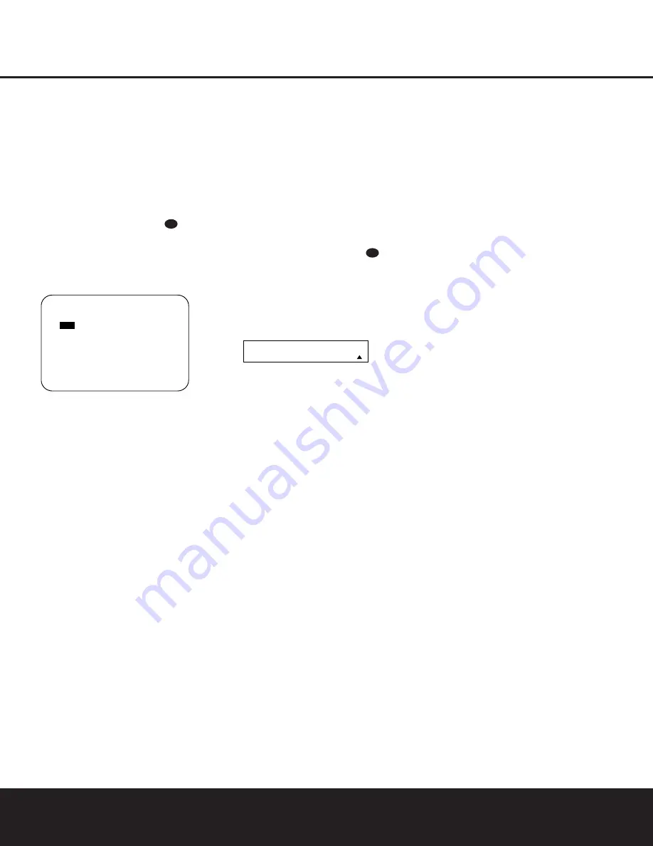
2. Press the 

Navigation Button

n

once to change

the bottom line of the remote’s LCD display to read

MANUAL SPL

as shown in Figure 12.

Figure 12

3. Press the 

Set Button

p

within five seconds to 

activate the remote’s manual mode, so that it functions
as an SPL meter. The right corner of the bottom line 
of the remote’s display will show the output level of 
the speakers as the test tone circulates. The level will
show as a direct SPL indication between 

66

d

B

and

79

d

B

. Below 

66

d

B

the remote will read 

LOW

and

above 

79

d

B

it will read 

HIGH

.

4. When you are finished with all adjustments, press the

Clear Button

9

to return the remote to normal

operation.

NOTE:

The subwoofer output level is not adjustable using

the test tone. To change the subwoofer level, follow the
steps for Output Level Trim Adjustment on page 29.

When all channels have an equal volume level, the adjust-
ment is complete. To exit this menu, press the 

/

¤

Navigation Buttons

n

until the on-screen 

cursor is

next to the 

BACK TO

MAIN

MENU

line, and then

press the 

Set Button

p

to return to the 

MAIN

menu.

The output levels may also be adjusted at any time using
the remote control and semi-OSD system. To adjust the
output levels in this fashion, press the 

Test Button

f

.

As soon as the button is pressed, the test tone will begin
to circulate as indicated earlier. The correct channel from
which the test noise should be heard will be shown in 
the lower third of the video screen and in the 

Main

Information Display

^

. While the test noise is circulat-

ing, the 

Speaker/Channel Input Indicator

E

for the

proper channel position will blink.

To adjust the output level, press the 

/

¤

Navigation

Buttons

n

until the desired level is shown in the dis-

play or on screen. Once the buttons are released, the test
noise will begin to circulate again in five seconds.

When all channels have the same output level, press the

Test Button

f

again to complete the process.

NOTE:

Output level adjustment is not available for the

VMAx or Surround Off mode.

Additional Input Adjustments

After one input has been adjusted for Surround mode,
digital input (if any), speaker type and output levels,
go back to the 

IN/OUT SETUP

line in the

MAIN

menu and enter the settings for each input that

you will use. In most cases, only the digital input and sur-
round mode will be different from one input to the next,
while the speaker type, crossover frequency, Night mode
and output level settings will usually be the same and may
be quickly entered by entering the same data used for the
original input.

Once the settings outlined on the previous pages have
been made, the DPR 1001 is ready for operation. While
there are some additional settings to be made, these are
best done after you have had an opportunity to listen to a
variety of sources and different kinds of program material.
These advanced settings are described on pages 30 and
31 of this manual. In addition, any of the settings made in
the initial configuration of the unit may be changed at any
time. As you add new or different sources or speakers, or
if you wish to change a setting to better reflect your listen-
ing taste, simply follow the instructions for changing the
settings for that parameter as shown in this section.

Having completed the setup and configuration process for
your DPR 1001, you are about to experience the finest in
music and home theater listening. Enjoy!

S E T   S P K R   L E V E L S

M A N U A L   S P L

44

*   C H A N N E L   A D J U S T   *

C E N     0 d B

F L :    

0 d B         F R :       0 d B

S L :     0 d B         S R :       0 d B

S B L :   0 d B         S B R :     0 d B

S U B     0 d B

C H A N N E L   R E S E T   : O F F

T E S T   T O N E           : O F F

R E T U R N   T O   M A I N   M E N U

31

Summary of Contents for DPR 1001

Page 1: ...DPR 1001 Digital Path Receiver Owner s Manual Power for the Digital Revolution...

Page 2: ...Functions 13 Zone II Remote Control Functions 14 Installation and Connections 16 System Configuration 16 Speaker Placement 17 Speaker Optimizer 18 Input Setup 18 Surround Setup 19 Speaker Setup 21 De...

Page 3: ...scan DVD players the DPR 1001 also features high bandwidth low crosstalk component video switching Coax and optical digital outputs are available for direct connection to digital recorders and both t...

Page 4: ...e top of the unit or place objects directly over them There is the remote possibility that the rubber padding on the bottom of the unit s feet may leave marks on certain wood or veneer materials Use c...

Page 5: ...ct Button 3 to scroll through the available choices until the desired mode appears in the Main Information Display F For more information see page 26 4 AM FM Selector Pressing this button will auto ma...

Page 6: ...he unit from the silenced condition E System Configuration Indicators One of these indicators will light after the Set Button has been pressed to indicate which configuration option is in use Press th...

Page 7: ...the number of channels available from the input source The left center right surround and surround back speaker indicators are composed of overlapping ovals while the subwoofer is represented by a sin...

Page 8: ...s to the PLAY OUT audio jacks on a VCR or other video source a b c d e f g i i j 31 32 36 h k 34 37 38 33 35 550W SWITCHED 50W 0 5A MAX SPEAKERS 8 LFE SUB FR FL LFE SUB FR FL FM Antenna AM Antenna Mul...

Page 9: ...should be connected to the red terminal on the Front Right speaker with the older color coding Connect the black terminal on the receiver to the matching black negative terminals for each front speake...

Page 10: ...und Mode Select Button 6 8 Channel Input Select SPL Select Button EzSet Microphone Sensor Lens NOTES The function names shown here are each button s feature when used with the DPR 1001 Most buttons ha...

Page 11: ...ak will change to monaural reception See page 28 for more information m Channel Select Button This button is used to start the process of setting the DPR 1001 s output levels to an external source Onc...

Page 12: ...Delay Select Press this button to begin the process for setting the delay times used by the DPR 1001 when processing surround sound After pressing this button the delay times are entered by pressing t...

Page 13: ...d in the room where the DPR 1001 is located press this button to raise or lower the volume in that room When it is used in a remote room with a sensor that is con nected to the Multiroom IR Jack this...

Page 14: ...ocal building codes in your area When connecting wires to the speakers be certain to observe proper polarity Note that the positive terminal of each speaker connection now carries a specific color cod...

Page 15: ...e obstruction may prevent the remote sensor from receiving commands In this event an optional remote infrared IR sensor may be used Connect the output of the remote sensor to the Remote IR Input Jack...

Page 16: ...ers are seated in the desired area Rear surround speakers are required when a full 7 1 channel system is installed and they may also be used as an alternative mounting position in a 5 1 channel sys te...

Page 17: ...king this adjustment you will need to find the impedance specification for your speakers This informa tion is often found on a label attached to the speaker and it is usually shown in the owner s manu...

Page 18: ...gital or DTS may not be changed Selection of the front panel jacks as an output will remain effective as long as the DPR 1001 is on Once the unit is turned off the jacks will revert to their normal us...

Page 19: ...Dolby Digital or DTS Digital soundtracks are in use See page 26 for a complete explanation of the Logic 7 Surround modes On the DSP menu the choices are the DSP surround modes designed for use with tw...

Page 20: ...rround channel When LARGE is selected a full range output will be sent to the surround channel outputs and NO surround channel signals will be sent to the subwoofer output When NONE is selected surrou...

Page 21: ...hen the Set Button p to return to the MAIN menu Delay Settings If Dolby Digital Dolby Pro Logic or DTS is selected as the surround mode for an input you may need to adjust the delay time setting The d...

Page 22: ...ured for their large or small settings as outlined above and turn off the OSD system if it is in use 2 Adjust the volume so that it is at 15dB as shown in the on screen display or Lower Display Line B...

Page 23: ...r The right corner of the bottom line of the remote s display will show the output level of the speakers as the test tone circulates The level will show as a direct SPL indication between 66dB and 79d...

Page 24: ...of which device such as the DVD or another video source is in use The factory setting for the remote is to have the Transport Forward Reverse Play Buttons G Transport Fast Play Scan Forward Reverse Bu...

Page 25: ...present in all stereo recordings However for stereo but not surround programs we suggest that you experiment with the other modes Surround modes may be selected using either the front panel controls...

Page 26: ...ther decoding techniques The Logic 7 M or Music mode should be used with analog or PCM stereo sources Logic 7 M enhances the listening experience by presenting a wider front soundstage and greater rea...

Page 27: ...tream Indicator A will light to show which type of signal is playing DOLBY D When the DOLBY D indicator lights a Dolby Digital bitstream is being received Depending on the settings on the source playe...

Page 28: ...ired frequency band is selected 3 Press the Tuning Mode Selector 7l to select manual or automatic tuning 4 To select stations press the Tuning Selector 8 w When the Auto Tuning mode is in use press an...

Page 29: ...to CHANNEL in the System Configuration Indicators Within five seconds press the Set Button again and the on screen display and the Lower Display Line B will change to FRONT L LEVEL indicating that th...

Page 30: ...e the default condition so that the same volume level is always used at turn on you will need to make an adjustment in the ADVANCED menu To start the adjustment press the OSD Button to bring the MAIN...

Page 31: ...ress the Navigation Button n until the MULTI ROOM line is highlighted Press the Set Button p to enter the MULTI ROOM menu Figure 14 Figure 14 When the MULTI ROOM menu appears the MULTI ROOM line will...

Page 32: ...her brand devices may be programmed into the DPR 1001 remote using its extensive library of remote codes or a head to head learning process for codes not in the internal library Thanks to the remote s...

Page 33: ...rogram the remote manually To automatically search through the codes that are available for a specific device type e g DVD VCR follow these steps 1 Turn on the power to the device you wish to program...

Page 34: ...device categories and press the Set Button p when the device for which you wish to set the codes appears For this example we will select TV to enter the codes needed to operate your TV 4 The next men...

Page 35: ...s used to control a VCR Press the Set Button F when the desired device combination appears Figure 36 5 Once the new device is selected the remainder of the process will select the codes for the specif...

Page 36: ...mple we first want the DPR to turn on so the Power Button 1 should be pressed Figure 42 8 Once the first command button for the macro has been pressed continue to press the buttons you wish to be part...

Page 37: ...nds for the video device Punch through enables you to easily program the remote to do this Volume Punch Through Follow these steps to enable the Volume Up Down and Mute controls from one device to be...

Page 38: ...pressed while the master device is in use Returning the Channel Control Settings to Default Operation If you wish to remove the Channel Punch Through so that the commands for Channel Up Down are retur...

Page 39: ...ton F again to immediately use the EzSet feature to calibrate the system as shown on pages 22 and 23 Renaming While the names given to the buttons and inputs on the DPR represent recognizable categori...

Page 40: ...main illuminated in red Press the Navigation Buttons n until RENAME appears on the bottom line of the LCD screen as shown in Figure 66 3 At the next menu screen press the Navigation Buttons n until RE...

Page 41: ...appear in the upper line of the remote s LCD screen as shown in Figure 75 It may take a few minutes for the reset process to take place and the length of time will vary depending on how much customiz...

Page 42: ...nput indicators Digital audio feed paused Resume play for DVD flash and digital audio stops Check that Digital Input is selected Processor Reset In the rare case in which the unit s operation or the d...

Page 43: ...tion 7 6W standby 550W rated output all channels driven Dimensions Width 17 3 inches 440mm Height 4 75 inches 120mm Depth 18 75 inches 476mm Weight 17 lb 7 7kg Depth measurement includes knobs buttons...

Page 44: ...250 Crossways Park Drive Woodbury New York 11797 www harmankardon com 2003 Harman International Industries Incorporated Part No YIAR L2000 01A...

Reviews: