Harman Kardon DPR 1001 Owner'S Manual Download Page 18

18

SYSTEM CONFIGURATION

SYSTEM CONFIGURATION

Input Setup

The first step in configuring the DPR 1001 is to config-
ure each input. When using the full-OSD system to make
the setup adjustments, press the 

OSD Button

once so that the 

MAIN

menu (Figure 1) appears.

The 

IN/OUT SETUP

line will be highlighted.

Press the 

Set Button

p

to enter the menu and the

IN/OUT SETUP

menu (Figure 2) will appear on

the screen. Press the 

/

Navigation Buttons

n

until the desired input name appears, as well as being
indicated in the front panel 

Input Indicators

&

by the

amber LED next to the desired input name. If the input
will use the standard left/right analog inputs, no further
adjustment is needed.
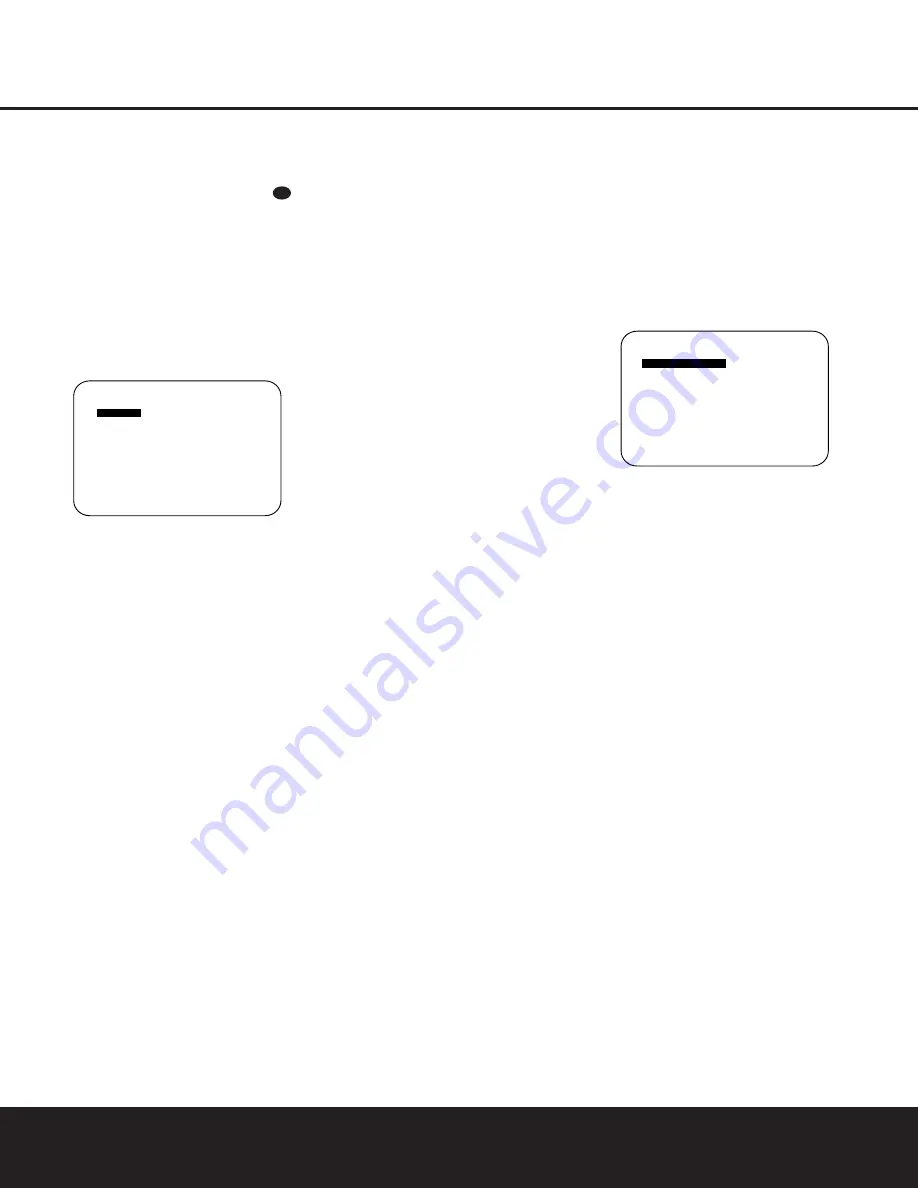
Figure 2

If you wish to associate one of the digital inputs with the
selected input source, press the 

¤

Navigation Button

n

while the 

IN/OUT SETUP

menu (Figure 2)

is on the screen, and the 

DIGITAL IN

line 

will be highlighted in reverse text. Press the 

/

Navigation Buttons

n

until the name of the desired

digital input appears. To return to the analog input, press
the buttons until the word 

ANALOG

appears.

When the correct input source appears, press the 

¤

Navigation Button

n

once so that 

RETURN

TO MAIN MENU

is highlighted, and press the 

Set

Button

p

.

To change the digital input at any time using the remote
control and the semi-OSD system, press the 

Digital

Select Button

o

. Within five seconds, make your

input selection using the 

/

¤

Navigation Buttons

n

until the desired digital or analog input is shown in

the 

Upper Display Line

F

and in the video display

connected to the DPR 1001. Press the 

Set Button

p

to enter the new digital input assignment.

To change the digital input from the front panel, press the

Set Button

!

and then press the 

/

¤

Buttons

)@

until the amber 

LED

is next to 

DIGITAL SELECT

in the 

System Configuration Indicators

%

on the right

side of the front panel and 

DIGI SEL MODE

appears in the 

Lower Display Line

B

. Within five sec-

onds, press the 

Set Button

!

again, and then press the

/

¤

Buttons

)@

again to cycle through the list of

available inputs. When the desired digital input (or the ana-
log input) name flashes in the right portion of the message
in the 

Upper Display Line

F

and in the on-screen dis-

play, press the 

Set Button

!

to enter your choice into

the unit’s memory. The DPR 1001 will return to normal
operation and displays within five seconds.

NOTE:

When a source such as an HDTV receiver 

or a digital cable set-top box is used, you may wish 
to connect both the coaxial digital output and the 
standard, analog output of the source to the DPR’s
VID 2 input since the program sources and channels
received by these devices often switch between 
analog and digital audio.

An exclusive Harman Kardon feature is the ability to
switch the front panel coaxial digital audio and analog
audio/video jacks from their normal use as inputs to out-
put connections so that portable recording devices may
easily be connected. On the DPR 1001, the 

Digital

Coax 3 Jack

Ò

is normally an input, but it may be

switched to a digital output for use with CD-R/RW decks,
MD recorders or other A/V recorders. To change the jack
to an output, press the 

/

¤

Navigation Buttons

n

while the 

IN/OUT SETUP

menu is on the screen

until 

COAXIAL 3

is highlighted. Then press the 

/

Navigation Buttons

n

so that the word 

OUT

appears. The 

Input/Output Status Indicator

will

turn red, indicating that the jack is now a record output.

NOTE:

A signal will be sent to this jack only when the

input selected for use by the DPR 1001 is digital. Digital
signals will be passed through regardless of their format,
and which digital input (optical or coax) they are fed
from. However, analog signals are not converted to digi-
tal, and the signal’s format (e.g., PCM, Dolby Digital or
DTS) may not be changed.

Selection of the front panel jacks as an output will remain
effective as long as the DPR 1001 is on. Once the unit
is turned off, the jacks will revert to their normal use as
an input when the unit is turned on again.

The front panel analog 

Video 4 Jacks

Ú

are normally

set as an input for use with camcorders, video games
and other portable audio/video products, but they may
be switched to an output for connection to portable
audio/video recorders. To temporarily switch them to out-
puts, you must first be at the 

IN/OUT SETUP

menu. Press the 

¤

Navigation Button

n

until the

VIDEO 4

line is highlighted. Press the 

Button

n

so that the word 

OUT

appears. Note that the

Input/Output Status Indicator

between the S-

and composite video jacks will turn red, indicating that
the analog Video 4 jacks are now record outputs.

Surround Setup

Once the basic input setup has been completed, the next
step is to select the surround mode you wish to use with
an input. Since surround modes are a matter of personal
taste, feel free to select any mode you wish – you may
change it later. However, to make it easier to establish
the initial parameters for the DPR 1001, it is best to
select Dolby Pro Logic II or Logic 7 for most analog
inputs and Dolby Digital for inputs connected to digital

sources. In the case of inputs such as a CD Player, Tape
Deck or Tuner, you may wish to set the mode to Stereo
(“Surround Off”) as they are not typically used with sur-
round-encoded material. Alternatively, the Logic 7 Music
mode is a good choice for two-channel source material.

It is easiest to complete the surround setup using the
full-OSD on-screen menus. From the 

MAIN

menu

(Figure 1), press the 

/

¤

Navigation Buttons

n

until 

SURROUND SELECT

is highlighted. Press

the 

Set Button

p

so that the 

SURROUND

SELECT

menu (Figure 3) is on the screen.

Figure 3

Each of the lines on the menu (Figure 3) contains a cat-
egory menu surround mode and within those menus you
may choose one of the sub-modes. The list of sub-
modes in some categories will vary according to whether
5.1 or 6.1/7.1 operation is chosen. Also, some of the
modes available in the DPR 1001 will not appear unless a
digital source is selected and playing the correct bitstream.

The selection of 5.1 or 6.1/7.1 configuration is deter-
mined by the setting for Surround Back Speakers in the
Speaker Setup menu. The factory setting is for “None,”
which will mean that only 5.1 modes will be available. To
utilize the 6.1/7.1 surround modes, change the setting
for the Surround Back Speakers to either Large or Small,
as shown in the instructions on page 20. This will auto-
matically activate all 6.1/7.1 surround mode options.

To select the mode that will be used as the initial default
for an input, first press the 

/

¤

Navigation Buttons

n

until the on-screen cursor is next to the desired

mode’s master category name. Next, press the 

Set

Button

p

to view the sub-menu. Press the 

/

Navigation Buttons

n

to scroll through the available

choices, and then press the 

¤

Navigation Button

n

so that the cursor is next to 

RETURN TO

MAIN MENU

to continue the setup process.

On the 

DOLBY SURR

menu (Figure 4), the choices

include Dolby Digital, Dolby Pro Logic II Music, Dolby 
Pro Logic II Movie, Dolby Pro Logic and Dolby 3 Stereo.
When a 6.1/7.1 speaker configuration is used,
Dolby Digital EX replaces the Dolby Digital mode. For a
complete explanation of these modes, see page 26. Note
that when a Dolby Digital mode is selected there are
additional settings available for the Night mode.

Note also that some of the available surround mode
combinations include both Dolby Digital and the various

*   S U R R O U N D   S E L E C T   *

D O L B Y   S U R R

D T S

L O G I C   7

D S P   ( S U R R )

V M A x  

S T E R E O

R E T U R N   T O   M A I N   M E N U

    *   I N / O U T   S E T U P   *    

I N P U T      

    : V I D E O   1

D I G I T A L   I N : A N A L O G

C O A X I A L   3   : I N

V I D E O   4       : I N  

R E T U R N   T O   M A I N   M E N U

31

Summary of Contents for DPR 1001

Page 1: ...DPR 1001 Digital Path Receiver Owner s Manual Power for the Digital Revolution...

Page 2: ...Functions 13 Zone II Remote Control Functions 14 Installation and Connections 16 System Configuration 16 Speaker Placement 17 Speaker Optimizer 18 Input Setup 18 Surround Setup 19 Speaker Setup 21 De...

Page 3: ...scan DVD players the DPR 1001 also features high bandwidth low crosstalk component video switching Coax and optical digital outputs are available for direct connection to digital recorders and both t...

Page 4: ...e top of the unit or place objects directly over them There is the remote possibility that the rubber padding on the bottom of the unit s feet may leave marks on certain wood or veneer materials Use c...

Page 5: ...ct Button 3 to scroll through the available choices until the desired mode appears in the Main Information Display F For more information see page 26 4 AM FM Selector Pressing this button will auto ma...

Page 6: ...he unit from the silenced condition E System Configuration Indicators One of these indicators will light after the Set Button has been pressed to indicate which configuration option is in use Press th...

Page 7: ...the number of channels available from the input source The left center right surround and surround back speaker indicators are composed of overlapping ovals while the subwoofer is represented by a sin...

Page 8: ...s to the PLAY OUT audio jacks on a VCR or other video source a b c d e f g i i j 31 32 36 h k 34 37 38 33 35 550W SWITCHED 50W 0 5A MAX SPEAKERS 8 LFE SUB FR FL LFE SUB FR FL FM Antenna AM Antenna Mul...

Page 9: ...should be connected to the red terminal on the Front Right speaker with the older color coding Connect the black terminal on the receiver to the matching black negative terminals for each front speake...

Page 10: ...und Mode Select Button 6 8 Channel Input Select SPL Select Button EzSet Microphone Sensor Lens NOTES The function names shown here are each button s feature when used with the DPR 1001 Most buttons ha...

Page 11: ...ak will change to monaural reception See page 28 for more information m Channel Select Button This button is used to start the process of setting the DPR 1001 s output levels to an external source Onc...

Page 12: ...Delay Select Press this button to begin the process for setting the delay times used by the DPR 1001 when processing surround sound After pressing this button the delay times are entered by pressing t...

Page 13: ...d in the room where the DPR 1001 is located press this button to raise or lower the volume in that room When it is used in a remote room with a sensor that is con nected to the Multiroom IR Jack this...

Page 14: ...ocal building codes in your area When connecting wires to the speakers be certain to observe proper polarity Note that the positive terminal of each speaker connection now carries a specific color cod...

Page 15: ...e obstruction may prevent the remote sensor from receiving commands In this event an optional remote infrared IR sensor may be used Connect the output of the remote sensor to the Remote IR Input Jack...

Page 16: ...ers are seated in the desired area Rear surround speakers are required when a full 7 1 channel system is installed and they may also be used as an alternative mounting position in a 5 1 channel sys te...

Page 17: ...king this adjustment you will need to find the impedance specification for your speakers This informa tion is often found on a label attached to the speaker and it is usually shown in the owner s manu...

Page 18: ...gital or DTS may not be changed Selection of the front panel jacks as an output will remain effective as long as the DPR 1001 is on Once the unit is turned off the jacks will revert to their normal us...

Page 19: ...Dolby Digital or DTS Digital soundtracks are in use See page 26 for a complete explanation of the Logic 7 Surround modes On the DSP menu the choices are the DSP surround modes designed for use with tw...

Page 20: ...rround channel When LARGE is selected a full range output will be sent to the surround channel outputs and NO surround channel signals will be sent to the subwoofer output When NONE is selected surrou...

Page 21: ...hen the Set Button p to return to the MAIN menu Delay Settings If Dolby Digital Dolby Pro Logic or DTS is selected as the surround mode for an input you may need to adjust the delay time setting The d...

Page 22: ...ured for their large or small settings as outlined above and turn off the OSD system if it is in use 2 Adjust the volume so that it is at 15dB as shown in the on screen display or Lower Display Line B...

Page 23: ...r The right corner of the bottom line of the remote s display will show the output level of the speakers as the test tone circulates The level will show as a direct SPL indication between 66dB and 79d...

Page 24: ...of which device such as the DVD or another video source is in use The factory setting for the remote is to have the Transport Forward Reverse Play Buttons G Transport Fast Play Scan Forward Reverse Bu...

Page 25: ...present in all stereo recordings However for stereo but not surround programs we suggest that you experiment with the other modes Surround modes may be selected using either the front panel controls...

Page 26: ...ther decoding techniques The Logic 7 M or Music mode should be used with analog or PCM stereo sources Logic 7 M enhances the listening experience by presenting a wider front soundstage and greater rea...

Page 27: ...tream Indicator A will light to show which type of signal is playing DOLBY D When the DOLBY D indicator lights a Dolby Digital bitstream is being received Depending on the settings on the source playe...

Page 28: ...ired frequency band is selected 3 Press the Tuning Mode Selector 7l to select manual or automatic tuning 4 To select stations press the Tuning Selector 8 w When the Auto Tuning mode is in use press an...

Page 29: ...to CHANNEL in the System Configuration Indicators Within five seconds press the Set Button again and the on screen display and the Lower Display Line B will change to FRONT L LEVEL indicating that th...

Page 30: ...e the default condition so that the same volume level is always used at turn on you will need to make an adjustment in the ADVANCED menu To start the adjustment press the OSD Button to bring the MAIN...

Page 31: ...ress the Navigation Button n until the MULTI ROOM line is highlighted Press the Set Button p to enter the MULTI ROOM menu Figure 14 Figure 14 When the MULTI ROOM menu appears the MULTI ROOM line will...

Page 32: ...her brand devices may be programmed into the DPR 1001 remote using its extensive library of remote codes or a head to head learning process for codes not in the internal library Thanks to the remote s...

Page 33: ...rogram the remote manually To automatically search through the codes that are available for a specific device type e g DVD VCR follow these steps 1 Turn on the power to the device you wish to program...

Page 34: ...device categories and press the Set Button p when the device for which you wish to set the codes appears For this example we will select TV to enter the codes needed to operate your TV 4 The next men...

Page 35: ...s used to control a VCR Press the Set Button F when the desired device combination appears Figure 36 5 Once the new device is selected the remainder of the process will select the codes for the specif...

Page 36: ...mple we first want the DPR to turn on so the Power Button 1 should be pressed Figure 42 8 Once the first command button for the macro has been pressed continue to press the buttons you wish to be part...

Page 37: ...nds for the video device Punch through enables you to easily program the remote to do this Volume Punch Through Follow these steps to enable the Volume Up Down and Mute controls from one device to be...

Page 38: ...pressed while the master device is in use Returning the Channel Control Settings to Default Operation If you wish to remove the Channel Punch Through so that the commands for Channel Up Down are retur...

Page 39: ...ton F again to immediately use the EzSet feature to calibrate the system as shown on pages 22 and 23 Renaming While the names given to the buttons and inputs on the DPR represent recognizable categori...

Page 40: ...main illuminated in red Press the Navigation Buttons n until RENAME appears on the bottom line of the LCD screen as shown in Figure 66 3 At the next menu screen press the Navigation Buttons n until RE...

Page 41: ...appear in the upper line of the remote s LCD screen as shown in Figure 75 It may take a few minutes for the reset process to take place and the length of time will vary depending on how much customiz...

Page 42: ...nput indicators Digital audio feed paused Resume play for DVD flash and digital audio stops Check that Digital Input is selected Processor Reset In the rare case in which the unit s operation or the d...

Page 43: ...tion 7 6W standby 550W rated output all channels driven Dimensions Width 17 3 inches 440mm Height 4 75 inches 120mm Depth 18 75 inches 476mm Weight 17 lb 7 7kg Depth measurement includes knobs buttons...

Page 44: ...250 Crossways Park Drive Woodbury New York 11797 www harmankardon com 2003 Harman International Industries Incorporated Part No YIAR L2000 01A...

Reviews: