Harman Kardon DPR 1001 Owner'S Manual Download Page 16

16

SYSTEM CONFIGURATION

SYSTEM CONFIGURATION

When all audio, video and system connections have
been made, there are a few configuration adjustments
that must be made. A few minutes spent to correctly
configure and calibrate the unit will greatly add to your
listening experience.

Speaker Selection and Placement

The placement of speakers in a multichannel home the-
ater system can have a noticeable impact on the quality
of sound reproduced.

No matter which type or brand of speakers is used, the
same model or brand of speaker should be used for the
left front, center and right front speakers. This creates a
seamless front soundstage and eliminates the possibility
of distracting sonic disturbances that occur when a sound
moves across mismatched front channel speakers.

Speaker Placement

Depending on the type of center channel speaker in use
and your viewing device, place the center speaker either
directly above or below your TV, or in the center behind
a perforated front projection screen.

Once the center channel speaker is installed, position the
front left and front right speakers so that they are as far
away from one another as the center channel speaker is
from the preferred listening position. Ideally, the front
channel speakers should be placed so that their tweeters
are no more than 24" above or below the tweeter in the
center channel speaker.

Depending on the specifics of your room acoustics and
the type of speakers in use, you may find that imaging is
improved by moving the left front and right front speakers
slightly forward of the center channel speaker. If possible,
adjust all front loudspeakers so that they are aimed at ear
height when you are seated in the listening position.

Using these guidelines, you’ll find that it takes some
experimentation to find the correct location for the front
speakers in your particular installation. Don’t be afraid to
move things around until the system sounds correct.
Optimize your speakers so that audio transitions across
the front of the room sound smooth, and that sounds
from all speakers appear to arrive at the listening position
at the same time (without delay from the center speaker
compared to the left and right speakers).

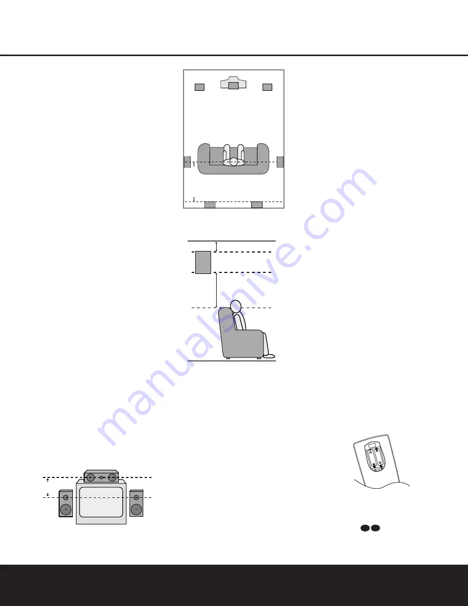
A) Front channel speaker installation with direct-view TV
sets or rear-screen projectors

B) Rear speaker mounting is an alternate location for 5.1
systems. It is required for 7.1 operation.

When the DPR 1001 is used in 5.1-channel operation,
the preferred location for surround speakers is on the
side walls of the room, at or slightly behind the listening
position. In a 7.1-channel system, both side surround
and back surround speakers are required. The center 
of the speaker should face into the room. The speakers
should be located so that the bottom of the cabinet is 
at least two feet higher than the listeners’ ears when the
listeners are seated in the desired area.

Rear surround speakers are required when a full 7.1-
channel system is installed, and they may also be used
as an alternative mounting position in a 5.1-channel sys-
tem when it is not practical to place the main surround
speakers on the sides of the room. Speakers may be
placed on a rear wall, behind the listening position.

As with the side speakers, rear surrounds should be

located so that the bottom of the cabinet is at least 
two feet higher than the listeners’ ears. The speakers
should be no more than six feet behind the rear of the
seating area.

Subwoofers produce nondirectional sound, so they may
be placed almost anywhere in a room. Actual placement
should be based on room size and shape and the type
of subwoofer used. One method of finding the optimal
location for a subwoofer is to begin by placing it in the
front of the room, about six inches from a wall, or near
the front corner of the room. Another method is to 
temporarily place the subwoofer at your normal listening
position, and then walk around the room until you find 
a spot where the subwoofer sounds best. Place the 
subwoofer in that spot. You should also follow the
instructions of the subwoofer’s manufacturer, or you 
may wish to experiment with the best location for a 
subwoofer in your listening room.

System Setup

Once the speakers have been placed in the room and
connected, the remaining steps in the setup process are
to program the DPR 1001’s bass management system
for the type of speakers used in your system, calibrate
the output levels, and set the delay times used by the
surround sound processor.

You are now ready to power up the DPR 1001 to begin
these final adjustments.

1. Plug the 

AC Power Cord

h

into an unswitched

AC outlet.

2. Open the door on the lower right corner of the front

panel to reveal the 

Main Power Switch

(

and

the other front panel jacks by gently pulling the door
down from the side of the unit where the word
OPEN appears. Press the 

Main Power Switch

(

in until it latches. Note that the 

Power Indicator

1

will turn red, indicating that the unit is in the

Standby mode.

3. Remove the protective plastic film from the front

panel lens. If left in place, the film may affect the
performance of your remote control.

4. Install the four supplied AAA batteries in the remote

as shown. Be certain to follow the (+) and (–)
polarity indicators that are printed inside the battery
compartment.

5. Turn the DPR 1001 on either by pressing the

Standby/On Button

2

on the front panel, or 

via the remote by pressing the 

Power On Button

b

, the 

AVR Selector

e

or any of the 

Input

Selectors

d

on the remote. The

Power Indicator 

1

will turn green to confirm that

the unit is on, and the 

Main Information Display

^

will also light.

43

34

At least 2 feet

At least 6 inches from ceiling 

Center Front

Speaker

Optional Rear-Wall Mounting

TV or Projection Screen

Right Front

Speaker

Left Front

Speaker

No more than 6 feet

when rear-mounted

speakers are used

Right Front
Speaker

Left Front

Speaker

No more

than 24"

Center Front Speaker

Summary of Contents for DPR 1001

Page 1: ...DPR 1001 Digital Path Receiver Owner s Manual Power for the Digital Revolution...

Page 2: ...Functions 13 Zone II Remote Control Functions 14 Installation and Connections 16 System Configuration 16 Speaker Placement 17 Speaker Optimizer 18 Input Setup 18 Surround Setup 19 Speaker Setup 21 De...

Page 3: ...scan DVD players the DPR 1001 also features high bandwidth low crosstalk component video switching Coax and optical digital outputs are available for direct connection to digital recorders and both t...

Page 4: ...e top of the unit or place objects directly over them There is the remote possibility that the rubber padding on the bottom of the unit s feet may leave marks on certain wood or veneer materials Use c...

Page 5: ...ct Button 3 to scroll through the available choices until the desired mode appears in the Main Information Display F For more information see page 26 4 AM FM Selector Pressing this button will auto ma...

Page 6: ...he unit from the silenced condition E System Configuration Indicators One of these indicators will light after the Set Button has been pressed to indicate which configuration option is in use Press th...

Page 7: ...the number of channels available from the input source The left center right surround and surround back speaker indicators are composed of overlapping ovals while the subwoofer is represented by a sin...

Page 8: ...s to the PLAY OUT audio jacks on a VCR or other video source a b c d e f g i i j 31 32 36 h k 34 37 38 33 35 550W SWITCHED 50W 0 5A MAX SPEAKERS 8 LFE SUB FR FL LFE SUB FR FL FM Antenna AM Antenna Mul...

Page 9: ...should be connected to the red terminal on the Front Right speaker with the older color coding Connect the black terminal on the receiver to the matching black negative terminals for each front speake...

Page 10: ...und Mode Select Button 6 8 Channel Input Select SPL Select Button EzSet Microphone Sensor Lens NOTES The function names shown here are each button s feature when used with the DPR 1001 Most buttons ha...

Page 11: ...ak will change to monaural reception See page 28 for more information m Channel Select Button This button is used to start the process of setting the DPR 1001 s output levels to an external source Onc...

Page 12: ...Delay Select Press this button to begin the process for setting the delay times used by the DPR 1001 when processing surround sound After pressing this button the delay times are entered by pressing t...

Page 13: ...d in the room where the DPR 1001 is located press this button to raise or lower the volume in that room When it is used in a remote room with a sensor that is con nected to the Multiroom IR Jack this...

Page 14: ...ocal building codes in your area When connecting wires to the speakers be certain to observe proper polarity Note that the positive terminal of each speaker connection now carries a specific color cod...

Page 15: ...e obstruction may prevent the remote sensor from receiving commands In this event an optional remote infrared IR sensor may be used Connect the output of the remote sensor to the Remote IR Input Jack...

Page 16: ...ers are seated in the desired area Rear surround speakers are required when a full 7 1 channel system is installed and they may also be used as an alternative mounting position in a 5 1 channel sys te...

Page 17: ...king this adjustment you will need to find the impedance specification for your speakers This informa tion is often found on a label attached to the speaker and it is usually shown in the owner s manu...

Page 18: ...gital or DTS may not be changed Selection of the front panel jacks as an output will remain effective as long as the DPR 1001 is on Once the unit is turned off the jacks will revert to their normal us...

Page 19: ...Dolby Digital or DTS Digital soundtracks are in use See page 26 for a complete explanation of the Logic 7 Surround modes On the DSP menu the choices are the DSP surround modes designed for use with tw...

Page 20: ...rround channel When LARGE is selected a full range output will be sent to the surround channel outputs and NO surround channel signals will be sent to the subwoofer output When NONE is selected surrou...

Page 21: ...hen the Set Button p to return to the MAIN menu Delay Settings If Dolby Digital Dolby Pro Logic or DTS is selected as the surround mode for an input you may need to adjust the delay time setting The d...

Page 22: ...ured for their large or small settings as outlined above and turn off the OSD system if it is in use 2 Adjust the volume so that it is at 15dB as shown in the on screen display or Lower Display Line B...

Page 23: ...r The right corner of the bottom line of the remote s display will show the output level of the speakers as the test tone circulates The level will show as a direct SPL indication between 66dB and 79d...

Page 24: ...of which device such as the DVD or another video source is in use The factory setting for the remote is to have the Transport Forward Reverse Play Buttons G Transport Fast Play Scan Forward Reverse Bu...

Page 25: ...present in all stereo recordings However for stereo but not surround programs we suggest that you experiment with the other modes Surround modes may be selected using either the front panel controls...

Page 26: ...ther decoding techniques The Logic 7 M or Music mode should be used with analog or PCM stereo sources Logic 7 M enhances the listening experience by presenting a wider front soundstage and greater rea...

Page 27: ...tream Indicator A will light to show which type of signal is playing DOLBY D When the DOLBY D indicator lights a Dolby Digital bitstream is being received Depending on the settings on the source playe...

Page 28: ...ired frequency band is selected 3 Press the Tuning Mode Selector 7l to select manual or automatic tuning 4 To select stations press the Tuning Selector 8 w When the Auto Tuning mode is in use press an...

Page 29: ...to CHANNEL in the System Configuration Indicators Within five seconds press the Set Button again and the on screen display and the Lower Display Line B will change to FRONT L LEVEL indicating that th...

Page 30: ...e the default condition so that the same volume level is always used at turn on you will need to make an adjustment in the ADVANCED menu To start the adjustment press the OSD Button to bring the MAIN...

Page 31: ...ress the Navigation Button n until the MULTI ROOM line is highlighted Press the Set Button p to enter the MULTI ROOM menu Figure 14 Figure 14 When the MULTI ROOM menu appears the MULTI ROOM line will...

Page 32: ...her brand devices may be programmed into the DPR 1001 remote using its extensive library of remote codes or a head to head learning process for codes not in the internal library Thanks to the remote s...

Page 33: ...rogram the remote manually To automatically search through the codes that are available for a specific device type e g DVD VCR follow these steps 1 Turn on the power to the device you wish to program...

Page 34: ...device categories and press the Set Button p when the device for which you wish to set the codes appears For this example we will select TV to enter the codes needed to operate your TV 4 The next men...

Page 35: ...s used to control a VCR Press the Set Button F when the desired device combination appears Figure 36 5 Once the new device is selected the remainder of the process will select the codes for the specif...

Page 36: ...mple we first want the DPR to turn on so the Power Button 1 should be pressed Figure 42 8 Once the first command button for the macro has been pressed continue to press the buttons you wish to be part...

Page 37: ...nds for the video device Punch through enables you to easily program the remote to do this Volume Punch Through Follow these steps to enable the Volume Up Down and Mute controls from one device to be...

Page 38: ...pressed while the master device is in use Returning the Channel Control Settings to Default Operation If you wish to remove the Channel Punch Through so that the commands for Channel Up Down are retur...

Page 39: ...ton F again to immediately use the EzSet feature to calibrate the system as shown on pages 22 and 23 Renaming While the names given to the buttons and inputs on the DPR represent recognizable categori...

Page 40: ...main illuminated in red Press the Navigation Buttons n until RENAME appears on the bottom line of the LCD screen as shown in Figure 66 3 At the next menu screen press the Navigation Buttons n until RE...

Page 41: ...appear in the upper line of the remote s LCD screen as shown in Figure 75 It may take a few minutes for the reset process to take place and the length of time will vary depending on how much customiz...

Page 42: ...nput indicators Digital audio feed paused Resume play for DVD flash and digital audio stops Check that Digital Input is selected Processor Reset In the rare case in which the unit s operation or the d...

Page 43: ...tion 7 6W standby 550W rated output all channels driven Dimensions Width 17 3 inches 440mm Height 4 75 inches 120mm Depth 18 75 inches 476mm Weight 17 lb 7 7kg Depth measurement includes knobs buttons...

Page 44: ...250 Crossways Park Drive Woodbury New York 11797 www harmankardon com 2003 Harman International Industries Incorporated Part No YIAR L2000 01A...

Reviews: