background image

20

INSTALLATION AND CONNECTIONS

Connecting a PC

If you wish to connect your PC to the screen, the
best way is to connect the DVI output of the com-
puter to the DVI Input 

K

on the rear panel of the

screen. At the same time connect the audio output
of your computer to the PC Audio Input 

I

on the

rear panel of the screen. If your PC does not have a
DVI output, but VGA only, use an adapter cable
VGA->DVI to connect your PC to the DVI input of
the screen. If the grafic card of your PC has also
other video outputs, please use any of the available
outputs of your computer to the matching input of
the screen.

Connecting a Digital Set Top Box or
Satellite Receiver

If you wish to connect your digital set top box or
satellite receiver to the screen, the best way is to
connect the HDMI output of the satellite receiver to
any of the HDMI 1 or HDMI 2 

RS

on the rear

panel of the screen. Both inputs are capable of
accepting up to 1080p signals.

Optional Audio Connections

Aux Input for External Source

You may connect a line-level stereo analog audio
source such as a Sat receiver, tape deck, phono pre-
amp of a record player, etc. to the controller's rear
panel AUDIO IN Input 

sockets to enjoy the bene-

fits of your system with other source components.

• VCR Connection-Audio (Cables Not Included). To

listen to the sound from your stereo VCR through
the speakers of this system, connect the Left/Right
audio output jacks of your stereo VCR to the
Left/Right audio input jacks AUDIO IN 

of this

system.

Aux Output for Recording

To record the sound of the system with your VCR or
any audio recording device (tape deck, MD, CDR
and some others.) the Audio Out jacks 

should be

connected to the analog Record In jacks of the
appropriate device. 

Digital In- and Outputs

Connect the optical digital output of any digital
sources such as an optional CD or DVD changer or
player, advanced video game, a digital satellite
receiver, HDTV tuner or digital cable set-top box or
the output of a compatible computer sound card to
the 

Optical Digital Inputs

1, 2 or 3 

PXW

.

The Coaxial Digital ouput of those devices may be
connected with the 

Coaxial Digital input 

P

on

the screen, (for PCM only) or the 

Coaxial Digital

Input

on the unit (for all formats), see page 19.

Connect the 

Coaxial Digital Output 

on the

rear panel of the Digital Lounge system to the
matching digital input connections on a CD-R or
MiniDisc recorder.

Note:

When connecting the optical digital audio

cable (optional).

n

Gently push the cable plug through the built-in
shutter that covers the optical digital audio out-
put and connect the cable firmly so that the con-
figurations of both the cable and the connector
match.

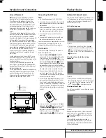
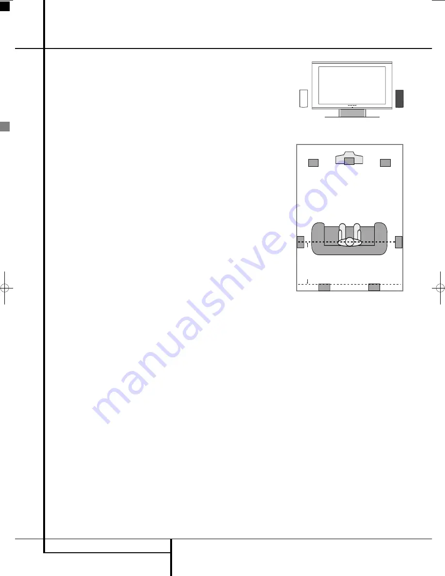
Speaker Placement

The placement of speakers in a multichannel
home-theater system can have a noticeable
impact on the quality of sound reproduced.
If you use the screen with the supplied table
stand, place the center loudspeaker in the desig-
nated place between the two feet of the stand.
Install the speaker from behind, and push it 
gently forward until it can not go any further.
If you do not wish to use the supplied table
stand, place the center speaker either directly
above or below your TV. A wall bracket is supplied
for the Center Speaker for this purpose. Once the
center-channel speaker is installed, position the
left-front and right-front speakers so that they are
as far away from one another as the center-chan-
nel speaker is from the preferred  listening position.
Ideally, the front-channel speakers should be
placed so that their tweeters are no more than
60cm above or below the tweeter in the center-
channel speaker. Depending on the specifics of
your room acoustics, you may find that imaging is
improved by moving the front-left and front-right
speakers slightly forward of the center-channel
speaker. If possible, adjust all front loudspeakers so
that they are aimed at ear height when you are
seated in the listening position.
Using these guidelines, you’ll find that it takes
some experimentation to find the correct location
for the front speakers in your particular installa-
tion. Don’t be afraid to move things around until
the system sounds correct. Optimize your speak-
ers so that audio transitions across the front of
the room sound smooth.
The preferred location for surround speakers is on
the side walls of the room, at or slightly behind
the listening position.
Rear surround speakers may also be used in 5.1
channel mode as an alternative mounting posi-
tion when it is not practical to place the main
surround speakers at the sides of the room.
Speakers may be placed on a rear wall, behind
the listening position. As with the side speakers,
the center of the rear surrounds should face you.
The speakers should be no more than 2 meters
behind the rear of the seating area.
The supplied pair of loudspeaker stands can be
used to either place the front- or rear loudspeak-
ers. Follow the instructions in the manual of the
stands for proper installation of the loudspeakers
on the stands.
Subwoofers produce largely nondirectional
sound, so they may be placed almost anywhere in
a room. Actual placement should be based on
room size. 

Installation and Connections

White

Red

A)  Front Channel Speaker Installation 
with table stand

Center Front

Speaker

Optional Rear-Wall Mounting

TV or Projection Screen

Right Front

Speaker

Left Front

Speaker

No more than 2m

when rear-mounted

speakers are used

B)  The distance between the left and right
speakers should be equal to the distance from
the seating position to the viewing screen. 
You may also experiment with placing the left
and right speakers slightly forward of the center
speaker. Rear speaker mounting is an alternate
location for 5.1 systems.

One method of finding the optimal location for a
subwoofer is to begin by placing it in the front
of the room, about 15cm from a wall, or near
the front corner of the room. Another method is
to temporarily place the subwoofer in the spot
where you will normally sit, and then walk
around the room until you find a spot where the
subwoofer sounds best. Place the subwoofer in
that spot.

0007CSK - DigitalLounge 632_640_646 ENG v11.qxp:0007CSK - DigitalLounge 632,640,646 UK  12/06/08  11:10  Side 20    (Sort/Black plade

Summary of Contents for DIGITAL LOUNGE 640

Page 1: ...ENGLISH Harman Kardon Digital Lounge 632 640 646 OWNER S MANUAL ...

Page 2: ...ain conventions have been used EXAMPLE bold type indicates a specific remote control or front panel button or rear panel connection jack EXAMPLE OCR type indicates a message that is visible on the front panel information display number in a square indicates a specific front panel control number in a circle indicates a rear panel connection 0 number in an oval indicates a button or indicator on the...

Page 3: ...dge will even let you charge your iPod An important addition to the Digital Lounge s impressive list of features is EzSet EQ which automates the configuration process to make it quicker easier and more precise Using the spe cial microphone supplied with the unit EzSet EQ takes the guesswork out of entering speaker size and crossover information delay times for all channels and output levels In add...

Page 4: ...home theater experience You may want to change some of the optional settings A description of all the optional settings and instructions for changing them are found in the second half of the manual This system was designed to provide you with many years of reliable operation with a minimum of care and maintenance Every component in your system was in perfect working condition when it left our fact...

Page 5: ...rman Kardon Digital Lounge product NEVER use benzene aerosol cleaners thinner alcohol or any other volatile cleaning agent Do not use abrasive cleaners as they may damage the finish of metal parts Avoid spraying insecticide near the system components Moving the Unit Before moving the system components be cer tain to disconnect any interconnection cords with other components and make certain that y...

Page 6: ...lows all of the lines in each frame odd and even to be shown at the same time Harman Kardon Digital Lounge comes with true progres sive scan video output resulting in a 40 greater light output than a conventional TV and a stun ningly detailed high definition image with absence of visible scanlines and motion artifacts Advanced Analog Signal Conversion AASC Technology Standard definition analog TV ...

Page 7: ... mix of features that are not compatible with the DVD Similarly although the DVD is capable of a wide range of features not all discs include every capability of the DVD system For example although the DVD is compatible with multi angle discs that feature is only possible when the disc is specially encoded for multi pleangle play In addition the DVD is capable of playing back both Dolby Digital an...

Page 8: ... USB hub The USB inputs are designed to power a single USB device at a time If additional hard disks are connected through a hub it is necessary that additional external power supplies are used to power the hub and hard disks 4 Headphone Jack This jack may be used to listen to the system s output through a pair of headphones Be certain that the headphones have a standard 3 5 mm stereo phone plug N...

Page 9: ...urrent track or the total remaining time on the disc When an iPod is playing the display will show the elapsed and remaining time on the top line The bottom line will scroll information about the song title album and artist NOTE The Indicators NOE will also display text messages about the DVD s status including Reading when a disc is loading STANDBY when the unit is turned off and Disc Error when ...

Page 10: ...ect to the supplied FM antenna Audio In Connect to a line level analog audio source TV tape player Minidisc PC etc Subwoofer Output Connect to the SUB LFE input on the subwoofer Coaxial Digital TV Input Connect the Coax Digital TV Output H of the screen to this jack using the supplied HDMI SP DIF Remote In Out cable Optical Digital Input Connect the optical digital output from a DVD player HDTV re...

Page 11: ...al recorder such as a CD R or MiniDisc recorder Subwoofer Trigger Output Connect this trigger output to the trigger input of the Harman Kardon subwoofer so that the sub woofer will switch on and off at the same time as the rest of the system Coaxial Digital Input Connect the coaxial digital output from a DVD player HDTV receiver LD player MD player satellite receiver or CD player to this jack The ...

Page 12: ...These inputs have no direct function in the system If you have optional video sources like a satellite receiver or VCR with a scart video output connect it to any of the two inputs In the TV Menu system these inputs are referred to as AV1 and AV2 G Power On Off Switch Press this button to switch the screen on or off H Coaxial Digital Audio TV Output Connect the Coax Digital TV Input of the DVD Rec...

Page 13: ...his input S HDMI 2 Input Connect any high definition video device that has a 1080p output to this input T Remote IR Input If you intend to point your remote control at the Source DVD unit to control your complete system connect one end of the supplied combined HDMI coaxial digi tal remote cable to this input and the other end to the Remote IR Output on the Source DVD unit U Remote IR Output If you...

Page 14: ...Button Skip Step Next Button Play Button Search Slow Reverse Button STOP Button Search Slow Forward Button Audio System On Source Selection Button Presets Button Zoom Button Playlist Button Random Button Learn Button Volume up down Button Light Button Numeric Key Buttons Repeat Button Clear Button OSD Button IR Transmitter Window Aspect Button Screen Power Buttons Info Button Teletext Buttons Pict...

Page 15: ...image in reverse frame by frame F Skip Step Next Button Press to go to beginning of next track After pressing the PAUSE button each press of this button will move the image forwards frame by frame G Play Button Begins to play disc closes disc tray first if it is open H Search Slow Rev Button Allows you to search in reverse through a disc while it is in play mode Each time you press this button the...

Page 16: ...de button changes the remote s mode in this order TV DVD VIDEO PC HDMI 1 HDMI 2 and HDMI 3 And then back to TV again The corresponding Source Selector will light to indicate the mode Important Note When toggling through the resolution modes by pressing this button repeatedly be sure to have your screen connected via HDMI or Component cable otherwise you will not see a picture with the progressive ...

Page 17: ...w Reverse Button Allows you to search in reverse through a disc while it is in play mode Each time you press this button the search speed changes as indicated by a number of arrows on the right top of your screen After pressing the PAUSE button each press of this button will change the slow down speed indicated by a number of arrows in the right top of the screen H LIGHT Button Press to illuminate...

Page 18: ...s with defects We request your understanding for the fact that such defects provided that they are within the limits specified by the standard cannot be con sidered to be as an appliance defect in the terms of the warranty If used for a long period of time as a PC screen shadows can occur on the screen as with any other TV set This phenomenon with LCD screens can be reduced by heeding the followin...

Page 19: ...or to the Remote Input of the screen and the other end to the Remote Input of the DVD Receiver Please note that you may run the remote signal both ways If you decide that it is easiest for you to control both screen and receiver by pointing the remote control towards the screen plug the remote cable into the Remote Control Out of the screen and into the Remote Control In of the receiver If your se...

Page 20: ...of the stand Install the speaker from behind and push it gently forward until it can not go any further If you do not wish to use the supplied table stand place the center speaker either directly above or below your TV A wall bracket is supplied for the Center Speaker for this purpose Once the center channel speaker is installed position the left front and right front speakers so that they are as ...

Page 21: ...in the room and connected the remaining steps are to program the system configuration memories First Turn On You are now ready to power up the system to begin final adjustments 1 Plug the Power Cable Q of the DVD receiver and TV into an unswitched AC outlet Press the Power On Switch G to the I position to switch on the TV to Standby mode Note that the Power Indicator 1 and the Power Indicator on t...

Page 22: ...complete you will be asked to save the new channels and you are informed how many channels were found If no channels are found check the antenna con nection If you have used and indoor antenna it may be necessary to use an outdoor antenna instead It may be a good idea to check with your TV network provider if there is DVB T coverage in your area at all If not use analog tuner or cable satellite re...

Page 23: ...selected or Off At the time of writing this age based system is not in use but plans are progressing to introduce age codes to be trans mitted along with the program content to exclude programs that are marked to be for chil dren older than the set limit You may also change the PIN code You will be asked to give the present code once the new code once and then once more to confirm Remember the new...

Page 24: ...ow modes Slow play is not available for CD Notes Playback features may not be available during the opening credits of a movie This is intended by the disc author and is not a failure of the Digital Lounge system Controller Playback of a DVD with 96 kHz 24 bit audio requires the use of circuitry normally used for other features Accordingly Slow Play Reverse and Step Advance features are not availab...

Page 25: ...Menus show the surround options for these spe cific audio inputs The USB Menu will show all information and options available when USB thumb devices or portable hard disks are con nected The DMP menu helps you browse through your music library once your iPod is con nected to your Bridge The SET UP Menu will help you configure all audio and video settings which are normally only made once As the co...

Page 26: ...nnel Color Balance The next line in the picture cali bration process is the Color Balance Setting allowing to adjust the color temperature Should you wish to change this setting press the Enter Button 6 once it is highlighted The TV Set Up Menu will be replaced temporarily by a Mini Bar on the right top of the screen allowing you to verify the changes made to the color balance setting in real time...

Page 27: ...next steps depend on which information about the TV station to add you have on hand Depending on whether you have the correct channel number or the correct frequency follow one of the two steps described below Channel Assigns the TV station s channel num ber If you know the correct channel number of the TV station to add press the Enter Button 6 once the line is highlighted The blue bar will dis a...

Page 28: ...vary the color temperature between green and purple in many small steps in contrast to the Color Balance setting It can be selected and changed in the same way as described for all other Picture Calibration settings on page 36 Figure 2i Set Up The DVD Set Up Menu permits changes to Film Mode Overscan and Interlaced Mode Film Mode This mode allows you to switch the Film Mode on or off When switched...

Page 29: ... whatever video resolution chosen The Film Mode can be turned on off directly also without the OSD opened by pressing the STATUS button with the remote in TV mode as long as the Teletext is not activated Exclusively for all analog inputs there is a setting for Picture Noise Compensation This should be used only for Still Pictures like JPEGs When turned on this feature will compen sate the low nois...

Page 30: ...ing or changing all settings and adjustments for both Audio and Video handling of your Digital Lounge system Press ENTER 6 to activate the SYSTEM Settings System Settings Figure 3e The System Setting Submenu contains the following settings Follow the explanations in the Upper Menu Line on the bottom of your screen to change the settings Display Language Sets the language in which the OSD menus are...

Page 31: ...of speaker size crossover delay and output level settings while adding the power of a multi band parametric equalizer to smooth out any peculiarities in frequency response that may result from the characteristics of the listening room With EzSet EQ your new receiver even alerts you to errors in speaker connections that prevent a speaker from functioning With EzSet EQ you are able to calibrate your...

Page 32: ... speaker is in the cor rect position For example it can tell whether a speaker is connected to the Surround Right out put but it cannot tell whether the speaker is on the right or left side of your listening room For that reason we strongly recommend that you try to listen as the tone circulates around you starting at the left front right front center and finishing at the left surround and right s...

Page 33: ...librated When that is done the Near Field process is complete With the cursor highlighting NEXT press the ENTER Button 6 to continue with the Subwoofer Far Field measurements Figure 6g Step 12 If a Near Field Error message appears as shown in Figure 6h you should check to make certain that the microphone is about one meter from the speaker being tested and that the top of the microphone unit is po...

Page 34: ...the configuration process for any surround sound product NOTE Listeners are often confused about the operation of the surround channels While some assume that sound should always be coming from each speaker most of the time there will be little or no sound in the surround channels This is because they are only used when a movie director or sound mixer specifically places sound there to create ambi...

Page 35: ...vice For more infor mation visit www divx com vod Follow the instructions and download the video onto a disc for playback on this unit Note that all the downloaded videos from DivX VOD can only be played back on this unit Once the DivX icon is highlighted press ENTER to access your personal DivX VOD code Figure 7c System Setup ...

Page 36: ...he KLN M Buttons 9 to select any of the calibration settings to be changed and follow the directions mentioned previously to find the right settings When the first calibration setting has been cor rectly made press the Enter Button 6 to go back to the Setup Menu Use the KL Buttons 9 to select the next calibration setting Once all calibration settings for the specific video input have been confirme...

Page 37: ... 6 while watching TV to call up the TV Channel menu or Favorite Channel menu press blue button from which you can choose channels directly On Screen Display Menu for the DVD receiver The On Screen Display of DVD receiver allows you to select any of the audio or audio video sources connected to the DVD receiver Press the DVD Button 0 followed by the OSD Button to call the OSD Menu for the DVD recei...

Page 38: ...can have the image files follow the audio signal at the end of each audio track the next JPEG image will be shown To activate this feature select Follow Audio Track in the Picture Setting With such discs you can also either listen to the MP3 audio or watch the JPEG video files only In order to do so in stop mode click on the LIST MUSIC FILES or LIST PICTURES icons on the left part of the screen to...

Page 39: ...e cursor will move to the Lower Menu Line of the screen 3 Select Remove from the list and press Enter 6 The cursor will move back to the original station line 4 Repeat step 3 until all radio stations you would like to delete have been removed Auto Preset function When the cursor is moved to the icon on top of the preset numbers you can activate the Auto Preset function clear the complete frequency...

Page 40: ...addition to the built in DVD Audio Video and CD player and the built in radio you can connect one more analog audio source to the DVD receiv er The analog source can be connected to the AUDIO IN input connectors on the rear panel 1 Press the AUX button K on the remote con trol to turn the DVD Receiver on and select Aux as the source Make sure your screen is switched on to be able to make the initi...

Page 41: ...ed to Discs s Order programming not possible with USB Repeat Sets the repeat mode Repeat All Repeat Folder Random Fixed to Off Random play not possible with USB Picture Selects the interval between the current picture on the screen and the next one In the USB Menu the chapter track or picture currently playing will be marked with an arrow symbol in front of the Track MP3 WMA Movie DivX XviD or Pic...

Page 42: ...on within the track with the elapsed and remaining times appearing below the bar Surround Mode Chart Dolby Digital Available only with digital input sources encoded with Dolby Digital data It pro vides up to five separate main audio channels and a special dedicated Low Frequency Effects channel DTS Available only with digital input sources encoded with DTS data Available on special High Definition...

Page 43: ...picture with the correct side ratio Dark stripes are visible on the left and right hand edges of the picture Fill all In this format setting the picture is adapted in horizontal direction until the screen s width is filled completelly This format is needed to display all so called Widescreen also named 16 9 or anamorphic movies with opti mal size and aspect ratio that will be streched vertically i...

Page 44: ...t be part of your system setup like the one from your TV To learn or transfer codes from an IR remote to the DL s remote follow these steps 1 Place the front of the original remote with the code being sent so that it is facing the IR Transmitter Window on the DL remote head to head The remotes should be between 2 and 4cm apart 2 Select the button on the remote that you wish to use as the device se...

Page 45: ...returns to the original code To erase all codes within a single device follow these steps 1 Press the Learn button P and the Device Selector Button in the System On group 0 together until the device button light remains on 2 Release the buttons 3 Press the same Device System On Button again 4 Press the 8 Button three times The Device Button blinks three times and goes out You are done NOTE When th...

Page 46: ...arian 7285 Icelandic 7383 Indonesian 7378 Interlingua 7365 Interlingue 7369 Iunpiak 7375 Irish 7165 Italian 7384 Japanese 7465 Javanese 7487 Kannada 7578 Kashmiri 7583 Kazakh 7575 Kinyarwanda 8287 Kirghiz 7589 Kirundi 8278 Korean 7579 Kurdish 7585 Laothian 7679 Latin 7665 Latvian Lettish 7686 Lingala 7678 Lithuanian 7684 Macedonian 7775 Malagsy 7771 Malay 7783 Malayalam 7776 Maltese 7784 Maori 777...

Page 47: ...heck that the speakers and components are connected securely Check that the connecting cords are away from a transformer or motor and at least 3 meters away from fluorescent light Move your TV away from the audio compo nents The plugs and jacks are dirty Wipe them with a cloth slightly moistened with alcohol Clean the disc Disconnect antenna cables from external sources also PC connected to the sc...

Page 48: ...does not operate properly Static electricity etc may affect the system s operation Disconnect the AC power cord then connect it again Please also refer to the Troubleshooting guide contained in your loudspeaker Owners Manual No picture although the mains plug is inserted and the unit is switched on Screen dark Weak or excessive colours The picture is too large or too small The displayed picture is...

Page 49: ...ause all channels are recorded discretely and processed digitally Manufactured under license from Digital Theater Systems Inc US Pat No 5 451 942 and other worldwide patents issued and pending DTS and DTS Digital Surround are trademarks of Digital Theater Systems Inc 1996 Digital Theater Systems Inc All rights reserved MPEG AUDIO International standard coding system to com press audio digital sign...

Page 50: ...CVBS input CVBS output Y C MiniDIN HOSIDEN YUV CVBS 3 x RCA Cinch HDTV CVBS RCA Cinch 4xHDMI digital video audio HDTV PC analogue digital connection DVI I analog RGB digital DVI 1 0 HDCP HDTV Stereo input 2 x 2 RCA Cinch L R 1Vrms YUV CVBS YC 1 x PC AUDIO IN 1 x RCA Cinch digital audio input DIG IN COAX 2 x SCART 1 Vrms Digital audio output 1 x RCA Cinch DIG OUT COAX Synchronization Sync on green ...

Page 51: ...solution More than 480 lines DVD Video signal to noise ratio More than 60 dB DVD Audio frequency response DVD PCM 20 Hz 22 kHz 1 0 dB Stereo CD PCM 20 Hz 20 kHz 1 0 dB Audio signal to noise ratio More than 80 dB PCM Total harmonic distortion Less than 0 01 PCM Dynamic range DVD PCM More than 85 dB EIAJ 2 kHz CD More than 85 dB EIAJ Amplifer output Power per channel 65 W 6ohms Signal to noise ratio...

Page 52: ...vity 86dB 1 Watt 1 meter Tweeter One 3 4 dome video shielded Midrange Dual 3 drivers video shielded Dimensions H x W x D 102mm x 241mm x 92mm Weight 1kg SUB TS11 Subwoofer Amplifier 200 Watts RMS Bass 10 Woofer bass reflex enclosure Dimensions H x W x D 479mm x 340mm x 340mm Weight 15kg All features and specifications are subject to change without notice Harman Kardon The Bridge and Logic 7 are re...

Page 53: ...53 ENGLISH ...

Page 54: ... Drive Woodbury New York 11797 516 422 HKHK 4545 Fax 516 682 3523 USA only www harmankardon com Harman Consumer Group Inc 2 route de Tours 72500 Château du Loir France 2008 Harman Kardon Incorporated Part No 04021804 532 ...

Reviews: