Harman Kardon BRUKSANVISNING AVR 355 Owner'S Manual Download Page 25

System Configuration

Number of Speakers

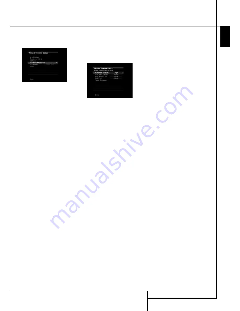
Move the cursor to the Number of Speakers line
and press the SetButton. See Figure 10.

Figure 10 – Number of Speakers Menu

The Number of Speakers menu lists each of the
speaker groups.

Program the correct setting for each group: ON
when the speakers are present in the system,
and OFF for positions where no speakers have-
been installed. The Front Left & Right speakers
are always ON and may not be disabled. Any
changes made to the system configuration will
be reflected in the total number speakers dis-
played at the top of the screen.

The setting for the surround back speakers
includes a third option:

Zone 2

. The AVR 355/

AVR 255 is among the few receivers in its class
that is capable of multizone operation, allowing
placement of a pair of speakers in another room
with listeners in the remote room enjoying either
the same program as in the main room or a dif-
ferent source. The AVR’s assignable surround
back amplifier channels make multizone opera-
tion easier than ever, since an external power
amplifier is no longer required. Simply select the
Zone 2 option at this line, and connect the
Surround Back Speaker Outputs to loudspeakers
located in the remote room. The main room will
be configured automatically for up to 5.1chan-
nels. See the Multizone Operation section for
more information.

The settings in this menu affect a number of
aspects of the AVR’s operation, including the
remainder of the speaker setup process and the
availability of various surround modes at any
time.

When you have finished programming the num-
ber of speakers in the system, select the Back
option to insure the settings are saved correctly.

You may use the Back/Exit Button, and the set-
tings will be saved.

Adjust Crossover Frequencies Menu

After you have programmed the number of
speakers in the system, the AVR will return to
the Manual Speaker Setup menu. Navigate to
the Crossover (Size) line and press the

OK

Button to display the Adjust Crossover
Frequencies menu (see Figure 11).

Figure 11 – Adjust Crossover Frequencies Menu

The AVR will only display those speaker groups
which you programmed in the Number of
Speakers menu.

Refer back to Step One, where you determined
each speaker’s crossover. Again, for the main
speakers, this is the lowest frequency the speak-
er reproduces well; and for the subwoofer, it’s
the highest.

For each main speaker, select one of the seven
crossover frequencies: 40Hz, 60Hz, 80Hz,
100Hz, 120Hz, 150Hz or 200Hz. If the crossover
frequency you determined in Step One is below
40Hz, select the first option, “Large”. This set-
ting doesn’t refer to the speaker’s physical size,
but to its frequency response, which is also
called “full range”. This means the speaker is
capable of playing sounds throughout the fre-
quencyspectrum, from the high pitches to the
bass.

Specify the size of the subwoofer’s transducer as
8, 10, 12 or 15 inches.

Make a note of each speaker group’s crossover
setting in Table A3 inthe appendix.

When you have finished entering the settings,
remember to select

Back

, not to press the Exit

Button.

Sub Mode

Move the cursor to the Sub Mode line to pro-
gram bass management for the subwoofer. The
subwoofer’s setting depends upon how you pro-
grammed the front left and right speakers.

• If you set the front speakers to a numeric

crossover frequency, the subwoofer setting will
be LFE, and you won’t be able to change it.

All low-frequency information will always be
sent to the subwoofer.

If you don’t have a subwoofer, we recommend
that you either upgrade to full-range speakers or
add a subwoofer to your systemat the earliest
opportunity.

• If you set the front speakers to LARGE, you

may select from two possible settings for the
subwoofer.

I

L/R+LFE: This setting sends all low-frequen-
cy information to the subwoofer, including
both information that would normally be
played through the front left and right
speakers and the special low-frequency
effects (LFE) channel information.

I

LFE: This setting plays low-frequency infor-
mation contained in the left and right pro-
gram channels to the front speakers, and
directs only the LFE channel information to
the subwoofer.

NOTE:

The Speaker/Channel Indicators on the

front panel of the receiver (see Figure on page
33) will display the speaker size settings as fol-
lows.
For each speaker configured numerically, a single
box will appear in the position for that speaker.
For each speaker configured as LARGE, a double
box will appear in its position. If a speaker is
configured as OFF, no box will appear. The sub-
woofer will be indicated by a single box, or no
box if no subwoofer has been configured. The
letters inside the boxes appear when a digital
signal is being received that has that channel
discretely encoded. The letters flash when the
signal is not present, such as when a DVD is
paused. A line will connect the SBL and SBR
boxes when a 6.1-channel signal is detected,
indicating that the same signal is playing
through both speakers.

E

N

G

L

IS

H

SYSTEM CONFIGURATION

25

Summary of Contents for BRUKSANVISNING AVR 355

Page 1: ...AVR 255 AVR 355 Audio VideoReceiver OWNER S MANUAL Composit AVR Info Resolution Audio Effects Video Modes Surround Modes Back Exit Source List A B L K OK ENGLISH...

Page 2: ...ource Name 22 Zone 2 Audio 22 Speaker Setup EzSet EQ 22 Speaker Setup Manual 28 Operation 28 Surround Mode Chart 30 Basic Operation 30 Mute Function 30 Audio Effects 30 Video Modes 30 Source Selection...

Page 3: ...s EzSet EQ also includes room equalization so that the signals sent to each speaker are tailored to provide accurate sonic quality with your specific combination of speaker type room size and other fa...

Page 4: ...nstructions Please read the following precau tions before use 1 Read these instructions 2 Keep these instructions 3 Heed all warnings 4 Follow all instructions 5 Do not use this apparatus near water 6...

Page 5: ...nces a fan may be required I Do not place the unit directly on a carpeted surface I Avoid installation in extremely hot or cold locations or an area that is exposed to direct sunlight or heating equip...

Page 6: ...deo Modes Button Source List Button Main Information Display Speaker Channel Input Indicator Surround Mode Button Back Exit Button Digital Optical Front Input Digital Coax Front Input Video Front Inpu...

Page 7: ...Main Information Display This display delivers messages and status indications to help you operate the receiver Speaker Channel Input Indicators These indicators are multipurpose indicating either th...

Page 8: ...onnections all connection jacks and terminals have been color coded in conformance with the latest CEA standards as follows Front Left White Front Right Red Center Green Surround Left Blue Surround Ri...

Page 9: ...to the black negative terminal on your speaker See page 16 for more information on speaker polarity Surround Speaker Outputs Connect these outputs to the matching and terminals on your surround channe...

Page 10: ...deo source HDMI Inputs Connect the HDMI output of video sources such as a DVD player set top box or HDTV tuner to either of these jacks Zone 2 Outputs AVR 355 only Connect these jacks to an optional a...

Page 11: ...utton Back Exit Button Master Volume Disc Menu Button Mute Button Surround Mode Button Learn Button AVR 355 only Device Power OFF Button Device Power ON Button Transmitter Window OK Button Settings Bu...

Page 12: ...tons serve as a ten button numeric keypad to enter tuner preset positions or track numbers with CD players changers or to tune stations directly Video Modes Button Press this button to go directly to...

Page 13: ...that is connected to the Zone 2 jack this button turns the Multi Room system off B AVR Settings Open the AVR settings info screen with this Button C Back Exit Button Press this button to go back to t...

Page 14: ...Sleep time selection J Settings Info Button Open the Settings Info Menu for any Source with this Button K Menu Button When using a H K DVD player with the receiver you can activate the DVD Menu with t...

Page 15: ...the video display is not compatible HDMI Input Connections The different Version levels of HDMI define which type of audio signals it is compatible with Based on the lowest level of HDMI among your s...

Page 16: ...ble the AM Loop Antenna supplied with the unit as shown below Connect it to the AM and GND screw terminals 6 Connect the supplied FM antenna to the FM 75 ohm connection The FM antenna may be an extern...

Page 17: ...source input then select the 6 8 channel analog audio inputs and the AVR will retain the last video source you selected 1 Connect a VCR s audio and video Play Out jacks to the Video 2 and Analog 4 In...

Page 18: ...R 355 Taking advantage of the AVR s built in seven channel amplifier it is possible to use two of the amplifi er channels to power speakers in the remote room When using this option you will not be ab...

Page 19: ...move things around until the system sounds correct Optimize your speakers so that audio transitions across the front of the room sound smooth When the AVR is used in 5 1 channel operation the preferre...

Page 20: ...ANT NOTE When viewing the on screen menus using a CRT based projector plasma display or any direct view CRT monitor or television it is important that they not be left on the screen for an extended pe...

Page 21: ...pending on the number of channels desired and a virtual surround mode if your system uses fewer than the full complement of seven main speakers plus a subwoofer Digital surround signals such as Dolby...

Page 22: ...enus from view You are now ready to begin enjoying your new receiver Speaker Setup With EzSet EQ you are able to calibrate your sys tem in a fraction of the time it would take to enter the settings ma...

Page 23: ...you are uncomfortable with or cannot tolerate loud sounds and do not use some sort of ear protection we strongly recommend that you leave the room and ask someone else to run the EzSet EQ process or...

Page 24: ...which speakers the receiver will use to playback the low frequency bass portion of the source program If you send the lowest notes to small satellite speakers you won t hear these notes very well and...

Page 25: ...the seven crossover frequencies 40Hz 60Hz 80Hz 100Hz 120Hz 150Hz or 200Hz If the crossover frequency you determined in Step One is below 40Hz select the first option Large This set ting doesn t refer...

Page 26: ...becomes both more critical and more complex Unlike the rotary balance control the goal of the AVR 355 AVR 255 s channel out put adjustment process is to examine the output level of each channel indepe...

Page 27: ...l automatically circulate to all channels pausing for a few moments at each channel and then moving to the next channel several seconds later as indicated by the highlight bar You may adjust the level...

Page 28: ...logy that decodes full range discrete left MOVIE center right right surround and left surround channels from matrix surround encoded programs and conventional stereo sources MUSIC when an analog input...

Page 29: ...pparent width of the sound across the front image is defined by the distance between the two speakers The Wide Mode provides a wider more spacious front image when the two speakers areclose together 5...

Page 30: ...on the specific characteristics of your listening room you may wish to tweak some of the audio settings such as tone controls to improve performance Access these settings from the Audio Effects Button...

Page 31: ...nalog audio outputs but not via its HDMI output Controls and Use of Headphones Adjust the volume to a comfortable level using the front panel Volume Control 1 or remote Volume Up Down P buttons To tem...

Page 32: ...Digital audio signals offer the benefit of greater capacity which allows recording artists to encode center and surround channel information directly into the signal The result is improved sound qual...

Page 33: ...d by the Dolby Pro Logic decoder in the AVR By default these signals are played in Dolby Pro Logic IIx Movie mode but you may select another Dolby surround mode manually Surround Modes Surround mode s...

Page 34: ...of audio video and still image materials on your iPod through your high quality audio video system Pressing the DMP Selector Button C will also activate the AVR remote s control codes for the iPod an...

Page 35: ...AVR needs to be configured for multiroom operation using the steps below Press the AVR button Y to bring the main menu to the screen Press the Button F until the ZONE 2 menu line is highlighted in bl...

Page 36: ...power amplifier connected to the Zone 2 Output jacks Although changes to the input source or Zone 2 volume will normally be made using an IR sensor in the remote room that is connected to the AVR it i...

Page 37: ...w the image pillarboxing When displaying full screen images on a widescreen device black or gray bars may appear to the left and right of the image Some displays especially plasma and CRT monitors may...

Page 38: ...s equipped with a number of advanced features that add extra flexibility to the unit s operation While it is not necessary to use these features to operate the unit they provide additional options tha...

Page 39: ...r them We recommend setting some timeout period to avoid the possibility of burn in damage to plasma or CRT displays Screen Saver Use this setting to program a timeout period for no activity with no m...

Page 40: ...e desired station has been tuned press the OK Button and two dashes will flash in the front panel display Use the Numeric Keys to enter the desired preset number and confirm with the OK Button If the...

Page 41: ...ts EDUCATE Educational DRAMA Drama CULTURE Culture SCIENCE Sciencek VARIED Varied Speech Programs POPM Popular Music ROCKM Rock Music M O R M Middle of the Road Music LIGHTM Classical Music CLASSICS S...

Page 42: ...fferent remote code 7 If the unit does not react to any code entered if the code for your product does not appear in the tables in the separate setup code guide or if not all functions operate properl...

Page 43: ...e original remote that you wish to teach into the AVR 355 remote When the Input Button on the AVR 355 blinks 3 times the code has been learned 6 Repeat steps 4 though 5 for each button on the source r...

Page 44: ...o change to the DVD mode Press the DEVICE POWER ON button to turn on the DVD Press the SAT device button to change to the SAT mode Press the DEVICE POWER ON button to turn on the SAT receiver 10 Press...

Page 45: ...rce Selector will light go dark and then light up again indicating the remote is in Program mode and that you may release the button 2 Select the type of punch through program ming a To program channe...

Page 46: ...t 26 0 0 0 0 0 0 0 2 27 Activity 28 Back Exit Back Exit Back Exit Back Exit Back Exit Back Exit Clear 29 Menu Menu Menu Menu Menu Menu Disc Menu 30 Light 31 Disc Menu Disc Menu 32 Left Left Left Left...

Page 47: ...6 6 6 6 6 6 6 6 6 6 22 7 7 7 7 7 7 7 7 7 7 23 8 8 8 8 8 8 8 8 8 8 24 9 9 9 9 9 9 9 9 9 9 25 Back Enter Prev Ch Instant Replay 26 0 0 0 0 0 0 0 0 0 0 27 28 Exit Return Back Exit Clear Exit Cancel Exit...

Page 48: ...1 17 3 3 3 3 3 3 3 1 18 4 4 4 4 4 4 4 1 19 5 5 5 5 5 5 5 1 20 6 6 6 6 6 6 6 2 21 7 7 7 7 7 7 7 2 22 8 8 8 8 8 8 8 2 23 9 9 9 9 9 9 9 2 24 Last Last Last Last Last 25 0 0 0 0 0 0 0 2 26 Activity 27 Bac...

Page 49: ...5 5 5 5 5 20 6 6 6 6 6 6 6 6 6 21 7 7 7 7 7 7 7 7 7 22 8 8 8 8 8 8 8 8 8 23 9 9 9 9 9 9 9 9 9 24 Back Enter Prev Ch Instant Replay 25 0 0 0 0 0 0 0 0 0 26 27 Return Back Exit Clear Exit Cancel Exit Cl...

Page 50: ...nction when Main No AC Power Make certain AC power cord is plugged Power Switch 1 is pushed into a live outlet Check to see if outlet is switch controlled Display lights but no sound Intermittent inpu...

Page 51: ...maximum AVR 355 Standby 3W 890W maximum 7 channels driven Dimensions Max Width 440mm Height 165mm Depth 382mm Weight net AVR 255 14 0 kg AVR 355 14 4 kg Depth measurement includes knobs buttons and t...

Page 52: ...log 4 inputs and outputs Composite OR S Video 2 input Coaxial Output and output Portable audio player AUX Any Stereo Jack use mini plug Not required cable not included Make this connection only when u...

Page 53: ...Level 0dB 0dB Surround Right Level 0dB 0dB Surround Back Right Level 0dB 0dB Surround Back Left Level 0dB 0dB Surround Left Level 0dB 0dB Sub Level 0dB 0dB Note The 6 8 Channel Inputs are direct inpu...

Page 54: ...ess 50 Contrast 50 Color 50 Sharpness 50 Picture Adjust Auto Fit Noise Reduction 0ff MPEG Noise Reduction 0ff Cross Color Suppressor Off Film Mode Detect Off Note These settings are only available whe...

Page 55: ...available when Dolby Pro Logic II or IIx Music mode has been selected Access these settings by selecting the Edit option Table A9 Remote Control Codes Source Input Device Type if changed Product Code...

Page 56: ...56 APPENDIX APPENDIX SETTINGS WORKSHEET Table A11 Zone 2 Settings Source Input Device Type if changed Your Settings Status Off Source Cable Sat Volume 25dB Surround Back Amps Main Room...

Page 57: ...APPENDIX 57 ENGLISH APPENDIX SETTINGS WORKSHEET...

Page 58: ...250 Crossways Park Drive Woodbury New York 11797 www harmankardon com Harman Consumer Group Inc 2 route de Tours 72500 Ch teau du Loir France 2008 Harman Kardon Incorporated Part No CQX1A1318Z...

Reviews: