Harman Kardon BRUKSANVISNING AVR 355 Owner'S Manual Download Page 24

System Configuration

Manual Setup

The AVR 355/AVR 255 is flexibly designed to be
used with almost any loudspeakers available. The
flexibility arises from the AVR 355/AVR 255’s
capability tobe configured to match the charac-
teristics of your particular speakers, and to com-
pensate for the acoustic characteristics of your
room.

EzSet/EQ automatically detects the capabilities of
each speaker, and optimizes the AVR 355/
AVR 255’s performance in your system. However,
if forsome reason you are unable to run
EzSet/EQ, e.g., you have misplaced the micro-
phone, or if you wish to make further adjust-
ments to the settings made by EzSet/EQ, you
may use the Manual Setup on-screen menus as
described in this section.

Before beginning manual setup place your loud-
speakers in their correct locations within the
room (see Speaker Placement section), and con-
nect them to the AVR. You will need the specifi-
cations for each of your speakers, which may
usually be found in the owner’s guide for the
speakers or on the manufacturer’s Web site. If
necessary, contact the manufacturer to obtain
the frequency range specification. Although the
output-level setting portion of manual setup may
be performed “by ear,” we recommend that you
purchase an SPL (sound-pressure level) meter at
a local electronics store.

We suggest that you record your configuration
settings in the appropriate places in Tables A3
through A7 in the appendix in case you need to
reenter them after a system reset, or if the AVR’s
Master Power Switch is turned off or the unit is
unplugged for more than four weeks.

Step One – Determine
Speaker Crossover

Without using EzSet/EQ, the AVR 355/ AVR 255
can’t detect how many speakers you’ve connect-
ed to it; nor can it determine their capabilities.
For this part of the system setup consult the
speaker’s technical specifications.

Locate the frequency response, which is usually
given as a range, e.g.,100Hz – 20kHz (±3dB).
This specification tells you whether the speaker is
able to play sounds that are very high- or low-
pitched, represented by the high and low fre-
quencies. We are concerned with the lowest fre-
quency that each of your main speakers is capa-
ble of playing, which is 100Hz in this example.
Use the Table A5 worksheet in the appendix to
note this number as the crossover for that speak-
er (not the same as the crossover frequency list-
ed in the speaker’s specifications).

The subwoofer’s frequency response will include
only the very lowest frequencies, since the sub-
woofer is designed to play only bass materials.

A typical frequency response for a subwoofer is
25Hz – 150Hz. In this case, the higher number
should be noted in the worksheet.

This information is required to program the
receiver’s bass management, which determines
which speakers the receiver will use to playback
the low-frequency (bass) portion of the source
program.

If you send the lowest notes to small satellite
speakers, you won’t hear these notes very well,
and you may even damage the speaker by
exceeding its capabilities. If you send the highest
notes to the special purpose subwoofer, you may
not hear them at all.

With proper bass management, the AVR 355/
AVR 255 divides the source signal at a crossover
point. All information above the crossover point
is played through the satellite speaker (front
left/right, center, surround left/right, or surround
back left/right), and all information below the
crossover point is played through the subwoofer.
This enables each loudspeaker in your system to
perform at its best, delivering an enjoyable
sound experience.

Step Two – Measure
Speaker Distances

Ideally, all of your speakers were placed in a cir-
cle, each at the same distance from the listening
position. However, your room may not be ideal,
and you may have had to place some speakers a
little further away than others. This could affect
the overall sound of the receiver, as sounds that
are supposed to arrive simultaneously from dif-
ferent speakers blur due to different arrival
times.

The AVR 355/AVR 255 has a delay adjustment
that enables the receiver to compensate for real-
world speaker placements.

Before you begin making adjustments, measure
the distance from each speaker to the listening
position, and note it in the Table A3 worksheet in
the appendix. Even if all of your speakers are the
same distance from the listening position, you
should enter your speaker distances as described
in Step Three.

Step Three – Manual Setup Menu

Now you are ready to program these adjust-
ments into the receiver. It’s best to sit in the
usual listening position and make the room as
quiet as possible.

With the receiver and video display turned on,
press the AVR Button on the remote to display
the menu system. Use the

L

Button to move

the cursor to the Speaker Setup line, and press
the

OK

Button to display the Speaker Setup

menu. See Figure 4.

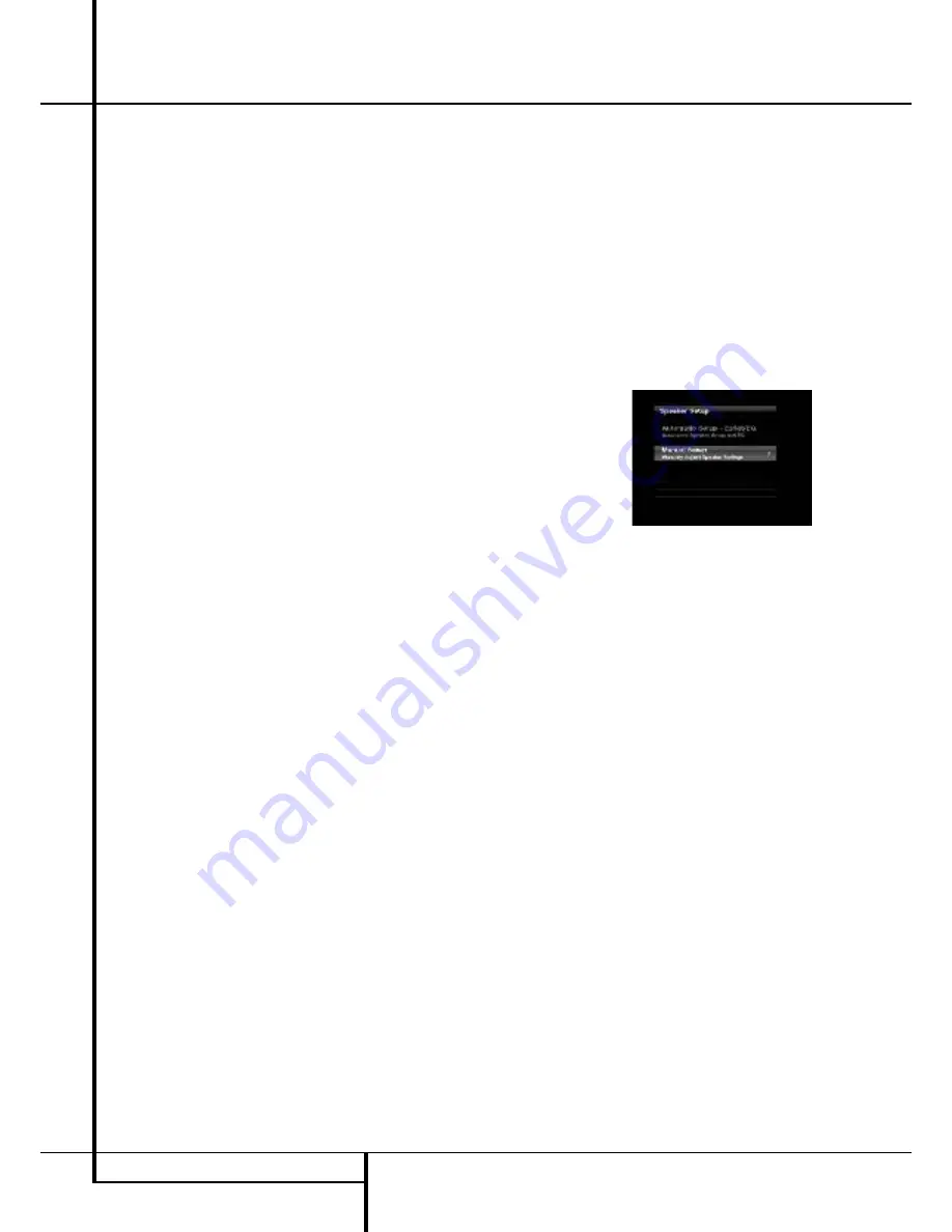
If you have run EzSet/EQ, those results were
saved. To tweak the EzSet/EQ results, or to con-
figure the AVR from scratch, select Manual
Setup. The screen shown in Figure 9 will appear.

Figure 9 – Manual Speaker Setup Menu

NOTE

: All of the speaker setup submenus

include the Exit and Back options as shown at
the bottom of Figure 9. To return to a previous
menu without making any changes, press Exit. To
save the current settings, select the Back option.

If you previously saved EzSet/EQ results in this
setup position and you wish to reconfigure the
speakers from scratch, select the Reset option.

For best results, we recommend configuring the
speakers in this order, although it may differ from
the order in which the submenus appear in the
Manual Speaker Setup menu: Number of
Speakers, Crossover(Size), Sub Mode, Distance
and Level Adjust.

24

SYSTEM CONFIGURATION

Summary of Contents for BRUKSANVISNING AVR 355

Page 1: ...AVR 255 AVR 355 Audio VideoReceiver OWNER S MANUAL Composit AVR Info Resolution Audio Effects Video Modes Surround Modes Back Exit Source List A B L K OK ENGLISH...

Page 2: ...ource Name 22 Zone 2 Audio 22 Speaker Setup EzSet EQ 22 Speaker Setup Manual 28 Operation 28 Surround Mode Chart 30 Basic Operation 30 Mute Function 30 Audio Effects 30 Video Modes 30 Source Selection...

Page 3: ...s EzSet EQ also includes room equalization so that the signals sent to each speaker are tailored to provide accurate sonic quality with your specific combination of speaker type room size and other fa...

Page 4: ...nstructions Please read the following precau tions before use 1 Read these instructions 2 Keep these instructions 3 Heed all warnings 4 Follow all instructions 5 Do not use this apparatus near water 6...

Page 5: ...nces a fan may be required I Do not place the unit directly on a carpeted surface I Avoid installation in extremely hot or cold locations or an area that is exposed to direct sunlight or heating equip...

Page 6: ...deo Modes Button Source List Button Main Information Display Speaker Channel Input Indicator Surround Mode Button Back Exit Button Digital Optical Front Input Digital Coax Front Input Video Front Inpu...

Page 7: ...Main Information Display This display delivers messages and status indications to help you operate the receiver Speaker Channel Input Indicators These indicators are multipurpose indicating either th...

Page 8: ...onnections all connection jacks and terminals have been color coded in conformance with the latest CEA standards as follows Front Left White Front Right Red Center Green Surround Left Blue Surround Ri...

Page 9: ...to the black negative terminal on your speaker See page 16 for more information on speaker polarity Surround Speaker Outputs Connect these outputs to the matching and terminals on your surround channe...

Page 10: ...deo source HDMI Inputs Connect the HDMI output of video sources such as a DVD player set top box or HDTV tuner to either of these jacks Zone 2 Outputs AVR 355 only Connect these jacks to an optional a...

Page 11: ...utton Back Exit Button Master Volume Disc Menu Button Mute Button Surround Mode Button Learn Button AVR 355 only Device Power OFF Button Device Power ON Button Transmitter Window OK Button Settings Bu...

Page 12: ...tons serve as a ten button numeric keypad to enter tuner preset positions or track numbers with CD players changers or to tune stations directly Video Modes Button Press this button to go directly to...

Page 13: ...that is connected to the Zone 2 jack this button turns the Multi Room system off B AVR Settings Open the AVR settings info screen with this Button C Back Exit Button Press this button to go back to t...

Page 14: ...Sleep time selection J Settings Info Button Open the Settings Info Menu for any Source with this Button K Menu Button When using a H K DVD player with the receiver you can activate the DVD Menu with t...

Page 15: ...the video display is not compatible HDMI Input Connections The different Version levels of HDMI define which type of audio signals it is compatible with Based on the lowest level of HDMI among your s...

Page 16: ...ble the AM Loop Antenna supplied with the unit as shown below Connect it to the AM and GND screw terminals 6 Connect the supplied FM antenna to the FM 75 ohm connection The FM antenna may be an extern...

Page 17: ...source input then select the 6 8 channel analog audio inputs and the AVR will retain the last video source you selected 1 Connect a VCR s audio and video Play Out jacks to the Video 2 and Analog 4 In...

Page 18: ...R 355 Taking advantage of the AVR s built in seven channel amplifier it is possible to use two of the amplifi er channels to power speakers in the remote room When using this option you will not be ab...

Page 19: ...move things around until the system sounds correct Optimize your speakers so that audio transitions across the front of the room sound smooth When the AVR is used in 5 1 channel operation the preferre...

Page 20: ...ANT NOTE When viewing the on screen menus using a CRT based projector plasma display or any direct view CRT monitor or television it is important that they not be left on the screen for an extended pe...

Page 21: ...pending on the number of channels desired and a virtual surround mode if your system uses fewer than the full complement of seven main speakers plus a subwoofer Digital surround signals such as Dolby...

Page 22: ...enus from view You are now ready to begin enjoying your new receiver Speaker Setup With EzSet EQ you are able to calibrate your sys tem in a fraction of the time it would take to enter the settings ma...

Page 23: ...you are uncomfortable with or cannot tolerate loud sounds and do not use some sort of ear protection we strongly recommend that you leave the room and ask someone else to run the EzSet EQ process or...

Page 24: ...which speakers the receiver will use to playback the low frequency bass portion of the source program If you send the lowest notes to small satellite speakers you won t hear these notes very well and...

Page 25: ...the seven crossover frequencies 40Hz 60Hz 80Hz 100Hz 120Hz 150Hz or 200Hz If the crossover frequency you determined in Step One is below 40Hz select the first option Large This set ting doesn t refer...

Page 26: ...becomes both more critical and more complex Unlike the rotary balance control the goal of the AVR 355 AVR 255 s channel out put adjustment process is to examine the output level of each channel indepe...

Page 27: ...l automatically circulate to all channels pausing for a few moments at each channel and then moving to the next channel several seconds later as indicated by the highlight bar You may adjust the level...

Page 28: ...logy that decodes full range discrete left MOVIE center right right surround and left surround channels from matrix surround encoded programs and conventional stereo sources MUSIC when an analog input...

Page 29: ...pparent width of the sound across the front image is defined by the distance between the two speakers The Wide Mode provides a wider more spacious front image when the two speakers areclose together 5...

Page 30: ...on the specific characteristics of your listening room you may wish to tweak some of the audio settings such as tone controls to improve performance Access these settings from the Audio Effects Button...

Page 31: ...nalog audio outputs but not via its HDMI output Controls and Use of Headphones Adjust the volume to a comfortable level using the front panel Volume Control 1 or remote Volume Up Down P buttons To tem...

Page 32: ...Digital audio signals offer the benefit of greater capacity which allows recording artists to encode center and surround channel information directly into the signal The result is improved sound qual...

Page 33: ...d by the Dolby Pro Logic decoder in the AVR By default these signals are played in Dolby Pro Logic IIx Movie mode but you may select another Dolby surround mode manually Surround Modes Surround mode s...

Page 34: ...of audio video and still image materials on your iPod through your high quality audio video system Pressing the DMP Selector Button C will also activate the AVR remote s control codes for the iPod an...

Page 35: ...AVR needs to be configured for multiroom operation using the steps below Press the AVR button Y to bring the main menu to the screen Press the Button F until the ZONE 2 menu line is highlighted in bl...

Page 36: ...power amplifier connected to the Zone 2 Output jacks Although changes to the input source or Zone 2 volume will normally be made using an IR sensor in the remote room that is connected to the AVR it i...

Page 37: ...w the image pillarboxing When displaying full screen images on a widescreen device black or gray bars may appear to the left and right of the image Some displays especially plasma and CRT monitors may...

Page 38: ...s equipped with a number of advanced features that add extra flexibility to the unit s operation While it is not necessary to use these features to operate the unit they provide additional options tha...

Page 39: ...r them We recommend setting some timeout period to avoid the possibility of burn in damage to plasma or CRT displays Screen Saver Use this setting to program a timeout period for no activity with no m...

Page 40: ...e desired station has been tuned press the OK Button and two dashes will flash in the front panel display Use the Numeric Keys to enter the desired preset number and confirm with the OK Button If the...

Page 41: ...ts EDUCATE Educational DRAMA Drama CULTURE Culture SCIENCE Sciencek VARIED Varied Speech Programs POPM Popular Music ROCKM Rock Music M O R M Middle of the Road Music LIGHTM Classical Music CLASSICS S...

Page 42: ...fferent remote code 7 If the unit does not react to any code entered if the code for your product does not appear in the tables in the separate setup code guide or if not all functions operate properl...

Page 43: ...e original remote that you wish to teach into the AVR 355 remote When the Input Button on the AVR 355 blinks 3 times the code has been learned 6 Repeat steps 4 though 5 for each button on the source r...

Page 44: ...o change to the DVD mode Press the DEVICE POWER ON button to turn on the DVD Press the SAT device button to change to the SAT mode Press the DEVICE POWER ON button to turn on the SAT receiver 10 Press...

Page 45: ...rce Selector will light go dark and then light up again indicating the remote is in Program mode and that you may release the button 2 Select the type of punch through program ming a To program channe...

Page 46: ...t 26 0 0 0 0 0 0 0 2 27 Activity 28 Back Exit Back Exit Back Exit Back Exit Back Exit Back Exit Clear 29 Menu Menu Menu Menu Menu Menu Disc Menu 30 Light 31 Disc Menu Disc Menu 32 Left Left Left Left...

Page 47: ...6 6 6 6 6 6 6 6 6 6 22 7 7 7 7 7 7 7 7 7 7 23 8 8 8 8 8 8 8 8 8 8 24 9 9 9 9 9 9 9 9 9 9 25 Back Enter Prev Ch Instant Replay 26 0 0 0 0 0 0 0 0 0 0 27 28 Exit Return Back Exit Clear Exit Cancel Exit...

Page 48: ...1 17 3 3 3 3 3 3 3 1 18 4 4 4 4 4 4 4 1 19 5 5 5 5 5 5 5 1 20 6 6 6 6 6 6 6 2 21 7 7 7 7 7 7 7 2 22 8 8 8 8 8 8 8 2 23 9 9 9 9 9 9 9 2 24 Last Last Last Last Last 25 0 0 0 0 0 0 0 2 26 Activity 27 Bac...

Page 49: ...5 5 5 5 5 20 6 6 6 6 6 6 6 6 6 21 7 7 7 7 7 7 7 7 7 22 8 8 8 8 8 8 8 8 8 23 9 9 9 9 9 9 9 9 9 24 Back Enter Prev Ch Instant Replay 25 0 0 0 0 0 0 0 0 0 26 27 Return Back Exit Clear Exit Cancel Exit Cl...

Page 50: ...nction when Main No AC Power Make certain AC power cord is plugged Power Switch 1 is pushed into a live outlet Check to see if outlet is switch controlled Display lights but no sound Intermittent inpu...

Page 51: ...maximum AVR 355 Standby 3W 890W maximum 7 channels driven Dimensions Max Width 440mm Height 165mm Depth 382mm Weight net AVR 255 14 0 kg AVR 355 14 4 kg Depth measurement includes knobs buttons and t...

Page 52: ...log 4 inputs and outputs Composite OR S Video 2 input Coaxial Output and output Portable audio player AUX Any Stereo Jack use mini plug Not required cable not included Make this connection only when u...

Page 53: ...Level 0dB 0dB Surround Right Level 0dB 0dB Surround Back Right Level 0dB 0dB Surround Back Left Level 0dB 0dB Surround Left Level 0dB 0dB Sub Level 0dB 0dB Note The 6 8 Channel Inputs are direct inpu...

Page 54: ...ess 50 Contrast 50 Color 50 Sharpness 50 Picture Adjust Auto Fit Noise Reduction 0ff MPEG Noise Reduction 0ff Cross Color Suppressor Off Film Mode Detect Off Note These settings are only available whe...

Page 55: ...available when Dolby Pro Logic II or IIx Music mode has been selected Access these settings by selecting the Edit option Table A9 Remote Control Codes Source Input Device Type if changed Product Code...

Page 56: ...56 APPENDIX APPENDIX SETTINGS WORKSHEET Table A11 Zone 2 Settings Source Input Device Type if changed Your Settings Status Off Source Cable Sat Volume 25dB Surround Back Amps Main Room...

Page 57: ...APPENDIX 57 ENGLISH APPENDIX SETTINGS WORKSHEET...

Page 58: ...250 Crossways Park Drive Woodbury New York 11797 www harmankardon com Harman Consumer Group Inc 2 route de Tours 72500 Ch teau du Loir France 2008 Harman Kardon Incorporated Part No CQX1A1318Z...

Reviews: