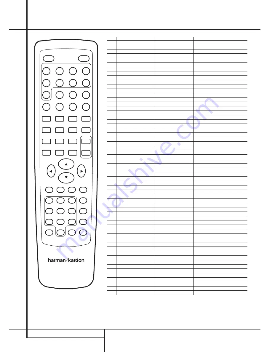
Harman Kardon AVR1550 Owner'S Manual Download Page 26

26

FUNCTION LIST

Function List 

1

2

3

7

11

15

16

17

18

19

20

21

22

23

24

25

26

27

28

29

30

31

32

33

34

35

36

37

38

39

40

41

42

43

44

45

46

47

48

49

50

51

52

53

54

55

56

57

58

12

13

14

8

9

10

4

5

6

AVR 1550

No.

Button Name

AVR Function

DVD Function

1

Power On

Power On

Power On

2

Power Off

Power Off

Power Off

3

AVR

AVR Select

AVR Select

4

DVD

DVD Select

DVD Select

5

CD

CD Input Select

6

TAPE

Tape Input Select

7

VID 1

Video 1 Select

8

VID 2

Video 2 Select

9

VID 3

Video 3 Select

10

TV

TV Input Select

11

FM/AM

Tuner Select

12

Audio

Audio Track Select

13

Subtitle

Subtitle Select

14

On/Off

Subtitle On/Off

15

Play

Play

16

Pause 

Pause

17

Stop

Stop

18

Status

Status Select

19

Tune Down

Tune Down

R. Search 

20

Tune Up 

Tune Up

F. Search

21

Preset Down

Preset Down

Skip Previous

22

Preset Up

Preset Up

Skip Next

23

Slow Reverse

Slow Reverse

24

Slow Forward

Slow Forward

25

Step Reverse

Step Reverse

26

Step Forward

Step Forward

27

Repeat

Repeat

28

Random

Random Play

29

Tun-M/Check

Tuner Mode

Check

30

Volume Up

Volume Up

Volume Up

31

Speaker/Menu

Speaker Adjust

Menu

32

Memory/Prog.

Tuner Memory

Program

33

Enter

Set

Enter

34

Volume Down

Volume Down

Volume Down

35

Move/Adjust Up

Up

36

Move/Adjust Left

Left

37

Move/Adjust Right

Right

38

¤

Move/Adjust Down

Down

39

Surround Select

Surround Select

40

Digital

Digital Input Select/Direct

41

Channel/Title

Channel Trim

Title

42

Delay

Delay Adjust

Open/Close

43

1

1

1

44

2

2

2

45

3

3

3

46

Test

Test Tone

47

4

4

4

48

5

5

5

49

6

6

6

50

Night

Night Mode Select

51

7

7

7

52

8

8

8

53

9

9

9

54

Sleep

Sleep

55

RDS

RDS Setup 

Menu

56

0

0

0

57

Clear

Clear

Clear

58

Mute

Mute

Summary of Contents for AVR1550

Page 1: ...AVR1550 Audio VideoReceiver OWNER S MANUAL Power for the Digital Revolution...

Page 2: ...p 24 Tuner Operation 24 RDS Operation 26 Function List 27 Troubleshooting Guide 27 Processor Reset 28 Technical Specifications Table of Contents Typographical Conventions In order to help you use this...

Page 3: ...ns In addi tion to Dolby Digital and DTS decoding for digi tal sources a broad choice of analog surround modes are available for use with sources such as CD VCR TV broadcasts and the AVR s own FM AM t...

Page 4: ...proper space is provided both above and below the unit for ventilation If this product will be installed in a cabinet or other enclosed area make certain that there is sufficient air movement within...

Page 5: ...eady to be turned on When the unit is in operation the indicator will turn green 4 Headphone Jack This jack may be used to listen to the AVR 1550 s output through a pair of headphones Be certain that...

Page 6: ...output level trim adjustment see page 23 Speaker Select Button Press this button to begin the process of selecting the speaker positions that are used in your listening room See page 14 for more info...

Page 7: ...nates if the RDS station tuned sometimes transmits traffic information see page 24 for more information on RDS L Tuned Indicator This indicator illuminates when a station is being received with suffic...

Page 8: ...amplifier is used connect this jack to the subwoofer amplifier input Video Monitor Outputs Connect these jacks to the composite and or S Video input of a TV monitor or video projector to view the out...

Page 9: ...ing on which device has been selected 3 Power Off Button Press this button to place the AVR 1550 in the Standby mode 4 Input Selectors Pressing one of these buttons will perform three actions at the s...

Page 10: ...keypad to enter tuner preset positions They are also used to select channel numbers when TV VCR or Sat receiver has been selected on the remote or to select track numbers on a compatible Harman Kardon...

Page 11: ...Cable with an area of 1 5 mm2 may be used for short runs of less than 4 m We do not recom mend that you use cables with an area less than 1mm2 due to the power loss and degradation in performance tha...

Page 12: ...R con nect the Out plugs to the Out jacks on the AVR Note that with some adapter types it may be just turned around If no signal is audible visi ble when the VCR is playing connect the Out plugs to th...

Page 13: ...ines you ll find that it takes some experimentation to find the correct location for the front speakers in your particular installation Don t be afraid to move things around until the system sounds co...

Page 14: ...input Remember since the AVR 1550 s memory system keeps the settings for each input sepa rate from the other inputs you will need to make these adjustments for each input used However once they are ma...

Page 15: ...SUR SPKR 8 Press the Enter button E on the remote control or the Set button on the front again and then use the buttons C on the remote or the Selector buttons on the front panel to select the option...

Page 16: ...olby Digital and DTS will only appear as choices when a digital input has been selected After the surround mode setting has been made with the current input repeat the setting with all inputs you will...

Page 17: ...e setting press the Input Source Selector on the front or 4 on the remote and select an input that is associated with a digital input and the Dolby Digital sur round mode Next press the Night button A...

Page 18: ...Trim Adjustment on page 23 When all channels have the same output level turn the Volume I down to about 40dB otherwise the listening level may be too high as soon as the source s music starts to play...

Page 19: ...ny of the Source Selector buttons on the remote 456 NOTE After pressing one of the Input Selector buttons 4 you must press the AVR Selector 5 to have the remote control the AVR functions The input sou...

Page 20: ...t signals The ProLogic II Emulation mode creates compelling five channel surround from conventional stereo recordings DOLBY 3 STEREO Uses the information contained in a surround encoded or two channel...

Page 21: ...indicator will also light up C D F H J Regard that any time a surround mode is changed it remains associated with the input just selected until another choice is made NOTE The name of each Surround M...

Page 22: ...ndicator A will light to show which type of signal is playing When the DOLBY D indicator lights a Dolby Digital bitstream is being received Depending on the audio track selected on the source player a...

Page 23: ...o mode can only be adjusted using this procedure To adjust the output levels using program mate rial first select the surround mode for which you want to trim the speakers see NOTE below by selecting...

Page 24: ...station using the steps outlined above Then 1 Press the Memory button Q on the remote Note that MEMORY indicator T will illuminate and flash in the Main Information Display 2 Within five seconds press...

Page 25: ...ds or downwards for the first station that has RDS data that matches the desired selec tion and acceptable signal strength for quality reception 4 The tuner will make up to one complete scan of the en...

Page 26: ...20 Tune Up Tune Up F Search 21 Preset Down Preset Down Skip Previous 22 Preset Up Preset Up Skip Next 23 Slow Reverse Slow Reverse 24 Slow Forward Slow Forward 25 Step Reverse Step Reverse 26 Step Fo...

Page 27: ...tain AC power cord is plugged Main Power Switch 1 is pushed into a live outlet Check to see if outlet is switch controlled Display lights but no sound Intermittent input connections Make certain that...

Page 28: ...age Rejection 80dB IF Rejection 90dB AM Tuner Section Frequency Range 520 1611kHz Signal to Noise Ratio 45dB Usable Sensitivity Loop 500 V Distortion 1kHz 50 Mod 0 8 Selectivity 9kHz 30dB Video Sectio...

Page 29: ...29...

Page 30: ...250 Crossways Park Drive Woodbury New York 11797 www harmankardon com Harman Consumer International 2 route de Tours 72500 Ch teau du Loir France 2002 Harman Kardon Incorporated Part No 55498730...

Reviews: