SYSTEM CONFIGURATION
SYSTEM CONFIGURATION
SYSTEM CONFIGURATION 25
SYSTEM CONFIGURATION 25
channel being adjusted will flash to indicate from
which channel the test tone should be heard. As
the adjustment proceeds, a few things will happen
simultaneously:
• The channel position being adjusted will flash in
the
Speaker/Channel Input Indicators
E
.
If the test noise is heard from a channel other
than the one shown in the indicator, there is an
error in the speaker connections. If this is the
case, press the
Test Button
i
TWICE to
stop the adjustment. Then, turn the unit off and
verify that all speakers are connected to the
proper
Outputs
§¶ª‚
.
• As the individual channels are set, the channel
name and the adjustment offset will appear in
the on-screen display (if connected) and the
Main Information Display
˜
. While the level
is changing, the
Program/SPL Indicator
c
will change colors to reflect the output level in
relation to the reference. A red indication shows
that the level is too high, while an amber indica-
tion shows that the level is too low. When the
indicator is green, the level is correct, and the
test noise will move to the next channel.
• While adjustments are being made, the red LED
under the
AVR Selector
f
will flash. This is
normal, and indicates that EzSet is operating.
7. After the test noise has circulated once through
each channel, it will send the tone to each chan-
nel once again, to verify the settings.
8. After two complete circulations of the tone, the
levels are set. The
Program/SPL Indicator
c
will remain green at each channel. Upon comple-
tion of the second circulation, the
Program/SPL
Indicator
c
will flash green twice and then go
out. The tone will stop and the AVR 525 will
return to normal operation.
If you find that the output levels chosen by EzSet are
either uncomfortably low or high, you may repeat the
procedure. Return to Step 2 and adjust the master
volume either slightly higher or lower to accommodate
your particular room layout and your tastes. You may
repeat this procedure as many times as necessary to
achieve a desired result. In order to prevent possible
damage to your hearing or your equipment, we
emphasize that you should avoid setting the master
volume above 0dB.
NOTE:
The subwoofer output is not adjusted when the
test tone is in use. To adjust the subwoofer output you
must use an external source, following the instructions
on page 32.
Manual Output Level Adjustment
Output levels may also be adjusted manually, either to
set them to a specific level with an SPL meter, or to
make fine tuning adjustments to the levels obtained
using the EzSet remote.
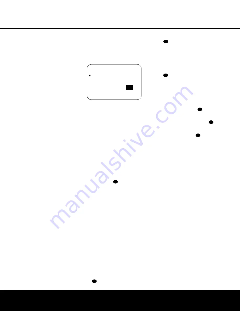
Figure 8
Manual output level adjustment is most easily done
through the
CHANNEL ADJUST
menu
(Figure 8). If you are already at the
MASTER
MENU
, press the
¤
Button
n
until the on-
screen
›
cursor is next to the
CHANNEL
ADJUST
line. If you are not at the
MASTER
MENU
, press the
OSD Button
v
to bring up the
MASTER MENU
(Figure 1), and then press the
¤
Button
n
until the on-screen
›
cursor is next
to the
CHANNEL ADJUST
line. Press the
Set
Button
p
to bring the
CHANNEL ADJUST
menu (Figure 8) to the screen.
When the
CHANNEL ADJUST
menu
appears, press the
¤
Button
n
until the on-screen
›
cursor is next to the
TEST TONE
line. Press
the
‹
/
›
Buttons
o
so that
ON
is highlighted
and the AVR’s internal test tone will begin to circulate
from speaker to speaker in a clockwise direction into
all speakers. The test noise will play for two seconds in
each speaker before circulating, and a blinking on-
screen cursor will appear next to the name of each
speaker location when the sound is at that speaker.
NOTE:
Remember to verify that the speakers have
been properly connected. As the test noise circulates,
listen to make certain that the sound comes from the
speaker position shown in the
Main Information
Display
˜
. If the sound from a speaker location
does NOT match the position indicated in the display,
turn the AVR 525 off using the
Main Power Switch
1
and check the speaker wiring or connections to
external power amplifiers to make certain that each
speaker is connected to the correct output terminal.
After checking for speaker placement, let the test
noise circulate again, and listen to see which channels
sound louder than the others. Using the front left
speaker as a reference, press the
‹
/
›
Buttons
o
on the remote to bring all speakers to the
same volume level. When one of the
‹
/
›
Buttons
o
is pushed, the test noise circulation will
pause on the channel being adjusted to give you time
to make the adjustment. When you release the button,
the circulation will resume after five seconds.
Continue to adjust the individual channels until the
volume level sounds the same from each speaker.
Adjustments should be made with the
‹
/
›
Buttons
o
on the remote only, NOT the main volume
controls. If you are using a sound-pressure level (SPL)
meter for precise level adjustment, set the volume so
that the meter reads 75dB, C-Weighting Slow.
You may also adjust the output levels manually while
using the level indication feature of the EzSet remote. To
activate the sensor and indicator, simply press and
release the
SPL Selector Button
on the remote
while the test tone is circulating. The
Program/SPL
Indicator
c
will change color to indicate the level.
Adjust the level using the
‹
/
›
Buttons
o
until
the LED lights green for all channels. When it is red, the
level is too high; when it is amber, the level is too low.
Press the
SPL Selector Button
when you are
finished to turn the sensor and indicator off.
NOTE:
The subwoofer level is not adjustable when the
normal test tone is in use. The subwoofer output level
may also be adjusted when the channel levels are
being trimmed to a program source rather than the
test tone, as shown on page 32.
When all channels have an equal volume level, the
adjustment is complete. To exit this menu, press the
⁄
/
¤
Buttons
n
until the on-screen
›
cursor is
next to the
BACK TO
MASTER
MENU
line,
and then press the
Set Button
p
to return to the
MASTER MENU
.
The output levels may also be adjusted at any time
using the remote control and semi-OSD system. To
adjust the output levels in this fashion, press the
Test
Button
i
. As soon as the button is pressed, the
test tone will begin to circulate as indicated earlier. The
correct channel from which the test noise should be
heard will be shown in the lower third of the video
screen and in the
Lower Display Line
B
. While the
test noise is circulating, the proper channel position will
also be indicated in the
Speaker/Channel Input
Indicators
E
by a blinking letter within the correct
channel.
To adjust the output level, press the
⁄
/
¤
Buttons
n
until the desired level is shown in the display or
on screen. Once the buttons are released, the test
noise will begin to circulate again in five seconds.
When all channels have the same output level, press
the
Test Button
i
again to complete the process.
41
37
41
37
37
37
37
* C H A N N E L A D J U S T *
F L
: 0 d B
S B R : 0 d B
C E N
: 0 d B
S B L : 0 d B
F R
: 0 d B
S L
: 0 d B
S R
: 0 d B
S U B : 0 d B
C H A N N E L R E S E T
:
O F F
O N
T E S T T O N E
:
O F F
O N
B A C K T O M A S T E R M E N U