


INSTALLATION AND CONNECTIONS
13
Installation and Connections
Speaker Selection
No matter which type or brand of speakers is
used, the same model or brand of speaker
should be used at least for the front-left, center
and front-right speakers. This creates a seamless
front soundstage and eliminates the possibility
of distracting sonic disturbances that occur when
a sound moves across mismatched front-channel
speakers.
Speaker Placement
The placement of speakers in a multichannel
home-theater system can have a noticeable
impact on the quality of sound reproduced.
Depending on the type of center-channel
speaker in use and your viewing device, place
the center speaker either directly above or below
your TV, or in the center behind a perforated
front-projection screen.
Once the center-channel speaker is installed,
position the left-front and right-front speakers so
that they are as far away from one another as
the center-channel speaker is from the preferred
listening position. Ideally, the front-channel
speakers should be placed so that their tweeters
are no more than 60cm above or below the
tweeter in the center-channel speaker.
They should also be at least 0.5 meter from your
TV set unless the speakers are magnetically
shielded to avoid colourings on the TV screen.
Note that most speakers are not shielded, even
with complete surround sets only the Center
speaker may be.
Depending on the specifics of your room
acoustics and the type of speakers in use, you
may find that imaging is improved by moving the
front-left and front-right speakers slightly
forward of the center-channel speaker. If
possible, adjust all front loudspeakers so that
they are aimed at ear height when you are
seated in the listening position.
Using these guidelines, you’ll find that it takes
some experimentation to find the correct
location for the front speakers in your particular
installation. Don’t be afraid to move things
around until the system sounds correct. Optimize
your speakers so that audio transitions across
the front of the room sound smooth.
Surround speakers should be placed on the side
walls of the room, at or slightly behind the
listening position. The center of the speaker
should face you.
If side-wall mounting is not practical, the
speakers may be placed on a rear wall, behind
the listening position. The speakers should be no
more than two meters behind the rear of the
seating area.
Subwoofers produce largely nondirectional
sound, so they may be placed almost anywhere
in a room. Actual placement should be based on
room size and shape and the type of subwoofer
used. One method of finding the optimal
location for a subwoofer is to begin by placing it
in the front of the room, about 15cm from a
wall, or near the front corner of the room.
Another method is to temporarily place the
subwoofer in the spot where you will normally
sit, and then walk around the room until you
find a spot where the subwoofer sounds best.
Place the subwoofer in that spot. You should
also follow the instructions of the subwoofer’s
manufacturer, or you may wish to experiment
with the best location for a subwoofer in your
listening room.
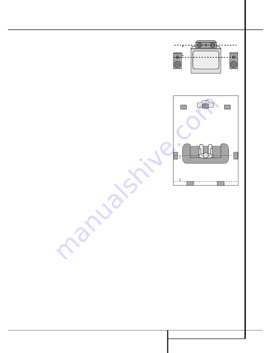
Right Front
Speaker
Left Front
Speaker
No more than
60cm
Center Front Speaker
A) Front Channel Speaker Installation with
Direct-View TV Sets or Rear-Screen Projectors
Center Front
Speaker
Optional Rear-Wall Mounting
TV or Projection Screen
Right Front
Speaker
Left Front
Speaker
No more than 2m
when rear-mounted
speakers are used
B) The distance between the left and right
speakers should be equal to the distance from
the seating position to the viewing screen.
You may also experiment with placing the left
and right speakers slightly forward of the center
speaker.


