AVR 1550
Audio/VideoReceiver
OWNER’S MANUAL
Power for the Digital Revolution
™
®
Page 1: ...AVR1550 Audio VideoReceiver OWNER S MANUAL Power for the Digital Revolution ...
Page 2: ...up 24 Tuner Operation 24 RDS Operation 26 Function List 27 Troubleshooting Guide 27 Processor Reset 28 Technical Specifications Table of Contents Typographical Conventions In order to help you use this manual with the remote control front panel controls and rear panel connections certain conventions have been used EXAMPLE bold type indicates a specific remote control or front panel button or rear ...
Page 3: ...ons In addi tion to Dolby Digital and DTS decoding for digi tal sources a broad choice of analog surround modes are available for use with sources such as CD VCR TV broadcasts and the AVR s own FM AM tuner In addition to providing a wide range of listening options the AVR 1550 is easy to configure so that it provides the best results with your speakers and specific listening room environment For t...
Page 4: ...t proper space is provided both above and below the unit for ventilation If this product will be installed in a cabinet or other enclosed area make certain that there is sufficient air movement within the cabinet Under some circumstances a fan may be required Do not place the unit directly on a carpeted surface Avoid installation in extremely hot or cold locations or an area that is exposed to dir...
Page 5: ...y to be turned on When the unit is in operation the indicator will turn green 4 Headphone Jack This jack may be used to listen to the AVR 1550 s output through a pair of headphones Be certain that the headphones have a standard 6 3 mm stereo phone plug Note that the speakers will automatically be turned off when the headphones are connected 5 Remote Sensor Window The sensor behind this window rece...
Page 6: ...output level trim adjustment see page 23 Speaker Select Button Press this button to begin the process of selecting the speaker positions that are used in your listening room See page 14 for more information on setup and configuration Video 3 Input Jacks These audio video jacks may be used for temporary connection to video games or portable audio video products such as camcorders and portable audio...
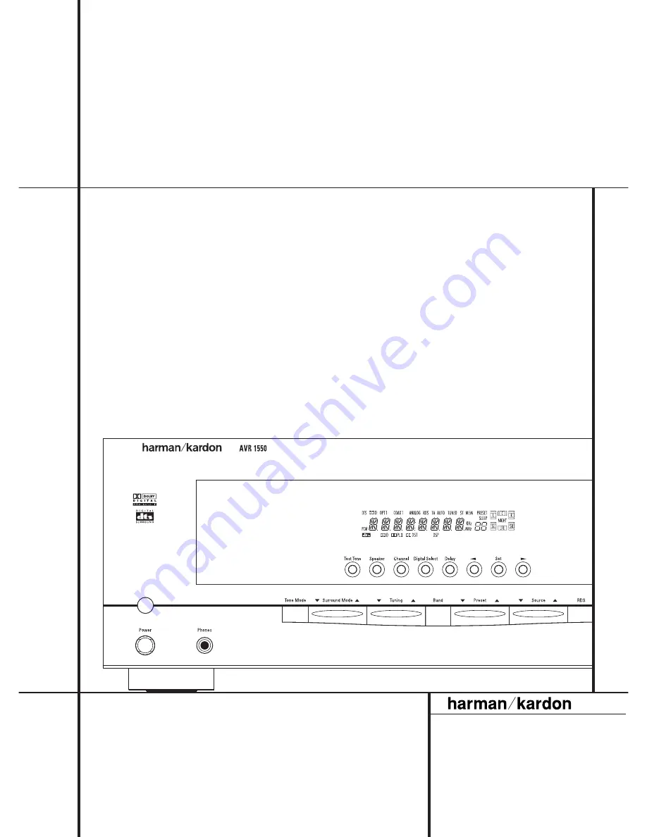
Page 7: ...inates if the RDS station tuned sometimes transmits traffic information see page 24 for more information on RDS L Tuned Indicator This indicator illuminates when a station is being received with sufficient sig nal strength to provide acceptable listening quality M Main Information Display This display shows messages relating to the status input source surround mode tuner volume level or other aspe...
Page 8: ...ofer amplifier is used connect this jack to the subwoofer amplifier input Video Monitor Outputs Connect these jacks to the composite and or S Video input of a TV monitor or video projector to view the output of any video source selected by the receiver s video switcher Front Center Speaker Outputs Connect these outputs to the matching or terminals on your front center speakers When making speaker ...
Page 9: ...ding on which device has been selected 3 Power Off Button Press this button to place the AVR 1550 in the Standby mode 4 Input Selectors Pressing one of these buttons will perform three actions at the same time First if the AVR is not turned on this will power up the unit Next it will select the source shown on the button as the input to the AVR Finally it will change the remote control so that it ...
Page 10: ... keypad to enter tuner preset positions They are also used to select channel numbers when TV VCR or Sat receiver has been selected on the remote or to select track numbers on a compatible Harman Kardon CD DVD or LD player H Tuner Mode Press this button when the tuner is in use to select between automatic tun ing and manual tuning When the button is pressed so that the AUTO indicator O goes out pre...
Page 11: ...2 Cable with an area of 1 5 mm2 may be used for short runs of less than 4 m We do not recom mend that you use cables with an area less than 1mm2 due to the power loss and degradation in performance that will occur Cables that are run inside walls should have the appropriate markings to indicate listing with UL CSA or other appropriate testing agency stan dards Questions about running cables inside...
Page 12: ...CR con nect the Out plugs to the Out jacks on the AVR Note that with some adapter types it may be just turned around If no signal is audible visi ble when the VCR is playing connect the Out plugs to the In jacks on the AVR and turned around If the adapter plugs are not labeled in that way pay attention to the signal flow direc Black Yellow Red Figure 1 SCART Cinch Adapter for playback signal flow ...
Page 13: ...lines you ll find that it takes some experimentation to find the correct location for the front speakers in your particular installation Don t be afraid to move things around until the system sounds correct Optimize your speakers so that audio transitions across the front of the room sound smooth Surround speakers should be placed on the side walls of the room at or slightly behind the listening p...
Page 14: ... input Remember since the AVR 1550 s memory system keeps the settings for each input sepa rate from the other inputs you will need to make these adjustments for each input used However once they are made further adjustment is only required when system components are changed To make this process as quick and as easy as possible we suggest that with each of these set tings to be made you step throug...
Page 15: ...o SUR SPKR 8 Press the Enter button E on the remote control or the Set button on the front Ó again and then use the buttons C on the remote or the Selector buttons on the front panel to select the option that best describes your system based on the Surround speaker definitions shown in preceding section When SMALL is selected with all digital sur round modes low frequency surround channel sounds w...
Page 16: ...Dolby Digital and DTS will only appear as choices when a digital input has been selected After the surround mode setting has been made with the current input repeat the setting with all inputs you will use The surround mode can also be changed at any time later and the AVR 1550 s memory system will keep the settings for the input selected until they are changed again Making Settings independent of...
Page 17: ... mode setting press the Input Source Selector on the front or 4 on the remote and select an input that is associated with a digital input and the Dolby Digital sur round mode Next press the Night button A on the remote When the button is pressed the words D R Dynamic Range followed by the current setting MID MAX OFF will appear in the Main Information Display M Press the buttons C within five seco...
Page 18: ...l Trim Adjustment on page 23 When all channels have the same output level turn the Volume I down to about 40dB otherwise the listening level may be too high as soon as the source s music starts to play After wards press the Test Tone Selector 7 button again to turn the test tone off and com plete the process IMPORTANT NOTE The Output level adjust ment made will be effective for the surround mode c...
Page 19: ...ny of the Source Selector buttons on the remote 456 NOTE After pressing one of the Input Selector buttons 4 you must press the AVR Selector 5 to have the remote control the AVR functions The input source may also be changed by pressing the front panel Input Source Selector button Each press of the button will move the input selection through the list of available inputs As the input is changed the...
Page 20: ...ht signals The ProLogic II Emulation mode creates compelling five channel surround from conventional stereo recordings DOLBY 3 STEREO Uses the information contained in a surround encoded or two channel stereo program to No surround channels create center channel information In addition the information that is normally sent to the rear channel surround speakers is carefully mixed in with the front ...
Page 21: ...e indicator will also light up C D F H J Regard that any time a surround mode is changed it remains associated with the input just selected until another choice is made NOTE The name of each Surround Mode will scroll through the Main Information Display M while the modes are being selected To avoid exiting from the surround mode selection process be certain to push the buttons C while a mode name ...
Page 22: ...am Indicator A will light to show which type of signal is playing When the DOLBY D indicator lights a Dolby Digital bitstream is being received Depending on the audio track selected on the source player and number of channels on the disc different surround modes are possible Note that only one channel without subwoofer called 1 0 audio or all five channels with subwoofer 5 1 audio or all steps bet...
Page 23: ...e can only be adjusted using this procedure To adjust the output levels using program mate rial first select the surround mode for which you want to trim the speakers see NOTE below by selecting the appropriate input associated with the desired surround mode start your program material source and set the reference volume for the front left and front right channels using the Volume Control I Once t...
Page 24: ... station using the steps outlined above Then 1 Press the Memory button Q on the remote Note that MEMORY indicator T will illuminate and flash in the Main Information Display 2 Within five seconds press the Numeric Keys G corresponding to the location where you wish to store this station s frequency Once entered the preset number will appear in the Preset Number Sleep Time Display Q 3 Repeat the pr...
Page 25: ...rds or downwards for the first station that has RDS data that matches the desired selec tion and acceptable signal strength for quality reception 4 The tuner will make up to one complete scan of the entire FM band for the next station that matches the desired PTY type and has accept able reception quality If no such station is found the display will read NONEfor some seconds and the tuner will ret...
Page 26: ...h 20 Tune Up Tune Up F Search 21 Preset Down Preset Down Skip Previous 22 Preset Up Preset Up Skip Next 23 Slow Reverse Slow Reverse 24 Slow Forward Slow Forward 25 Step Reverse Step Reverse 26 Step Forward Step Forward 27 Repeat Repeat 28 Random Random Play 29 Tun M Check Tuner Mode Check 30 Volume Up Volume Up Volume Up 31 Speaker Menu Speaker Adjust Menu 32 Memory Prog Tuner Memory Program 33 E...
Page 27: ...rtain AC power cord is plugged Main Power Switch 1 is pushed into a live outlet Check to see if outlet is switch controlled Display lights but no sound Intermittent input connections Make certain that all input and speaker or picture connections are secure Mute is on Press Mute button 2 Volume control is down Turn up volume control Sound is heard but Front Panel Display brightness is turned off Fo...
Page 28: ...Image Rejection 80dB IF Rejection 90dB AM Tuner Section Frequency Range 520 1611kHz Signal to Noise Ratio 45dB Usable Sensitivity Loop 500µV Distortion 1kHz 50 Mod 0 8 Selectivity 9kHz 30dB Video Section Video Format PAL NTSC Input Level Impedance 1Vp p 75 ohms Output Level Impedance 1Vp p 75 ohms Video Frequency Response 10Hz 8MHz 3dB General Power Requirement AC 220 240V 50Hz Power Consumption 7...
Page 29: ...29 ...
Page 30: ...250 Crossways Park Drive Woodbury New York 11797 www harmankardon com Harman Consumer International 2 route de Tours 72500 Château du Loir France 2002 Harman Kardon Incorporated Part No 55498730 ...