background image

System Setup

Once the speakers have been placed in the
room and connected, the remaining steps in
the setup process are to program the AVR 100’s
bass management system for the type of
speakers used in your system, calibrate the
output levels, and set the delay times used by
the surround-sound processor.

You are now ready to power up the AVR 100 to
begin these final adjustments.

1. Plug the 

Power Cable

into an

unswitched AC outlet.

2. Press the 

Main Power Switch

1

in so

that it latches in and is flush with the front
panel. Note that the 

Power Indicator

3

will turn amber, indicating that the unit is
in the Standby mode.

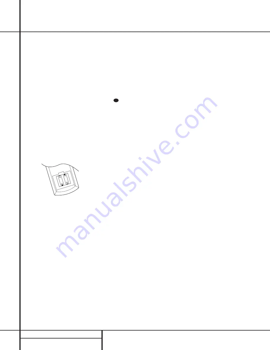
3. Install the four supplied AAA batteries in

the remote as shown. Be certain to follow
the (+) and (–) polarity indicators that are
on the bottom of the battery compartment.

4. Turn the AVR 100 on either by pressing the

System Power Control

2

on the front

panel, or via the remote by pressing a

Device Selector

a

on the remote. The

Power Indicator 

3

will turn green to con-

firm that the unit is on, and the 

Information

Display

35  

will also light up.

Speaker Configuration

The first few adjustments tell the AVR 100
which type of speakers are in use. This is
important as it adjusts the settings that deter-
mine which speakers receive low-frequency
(bass) information. For each of these settings
use the 

LARGE

setting if the speakers for a

particular position are traditional full-range
loudspeakers that are capable of reproducing
sounds below 100Hz. Use the 

SMALL

set-

ting for smaller, frequency-limited satellite
speakers that do not reproduce sounds below
100Hz. Note that when “small” speakers are
used, a subwoofer is required to reproduce
low-frequency sounds. Remember that the
“large” and “small” descriptions do not refer
to the actual physical size of the speakers, but
their ability to reproduce low-frequency

sounds. If you are in doubt as to which cat-
egory describes your speakers, consult the
specifications in the speakers’ owner’s manual,
or ask your dealer.

With the AVR 100 turned on, follow these steps
to configure the speakers:

1. Put the AVR 100 in the Dolby Pro Logic

mode by pressing the 

Dolby Pro Logic

Selector

Ô

on the front panel or by

pressing the 

Surround Mode Selectors

on the remote, until 

PRO LOGIC

appears in the 

Main Information Display

N

and the 

PRO LOGIC

indicator 

B

lights.

2. Press the 

Speaker

button 

fl

33 

on the

remote or front panel. The words 

FRNT

SPEAKER

will appear in the 

Main

Information Display

N

.

3. Press the 

Set

button 

t 31  

and note

that the 

pointer will stop flashing.

4. Press the 

/

buttons 

r

on the remote

or the 

Selector

buttons 

34

on the front

panel until either 

LARGE

or 

SMALL

appears, matching the type of speakers you
have at the left-front and right-front posi-
tions, as described by the definitions
shown in preceding section.

When 

SMALL

is selected, low-frequency

sounds will be sent to the subwoofer output
only. Note that if you choose this option,
and there is no subwoofer connected, you
will not hear any low-frequency sounds from
the front channels.

When 

LARGE

is selected, a full-range out-

put will be sent to the front-left and front-
right outputs, and NO low-frequency signals
will be sent to the subwoofer output.

5. When you have completed your selection for

the front channel, press the 

Set

button

t 31 

, and then press the 

/

buttons

r

on the remote or the 

Selector

buttons

34

on the front panel to change the dis-

play to 

CEN SPEAKER

.

6. Press the 

Set

button 

t 31 

again, and

use the 

/

buttons 

r

on the remote,

or the 

Selector

buttons 

34

on the front

panel, to select the option that best
describes your system based on the speaker
definitions shown in preceding section.

When 

CEN SP SMALL

is selected,

low-frequency center-channel sounds will be
sent to the subwoofer output only. Note
that if you choose this option and there is
no subwoofer connected, you will not hear
any low-frequency sounds from the center-
channel speaker.

When 

CEN SP LARGE

is selected, a

full-range output will be sent to the center-
speaker output, and NO center channel sig-
nal will be sent to the subwoofer output.

When 

CEN SP NONE

is selected, no

signals will be sent to the center-channel
output. The receiver will operate in a
“phantom” center-channel mode and 
center-channel information will be sent to
the left- and right-front channel outputs.

7. When you have completed your selection

for the center channel, press the 

Set

button 

t 31 

, and then press the 

/

buttons 

r

on the remote or the

Selector

buttons 

34

on the front 

panel to change the display to 

SUR

SPEAKER

.

8. Press the 

Set

button 

t 31 

again, and

then use the 

/

buttons 

r

on the

remote or the 

Selector

buttons 

34 

on the

front panel to select the option that best
describes your system based on the speaker
definitions shown in preceding section.

When 

SUR SP SMALL

is selected,

low-frequency surround-channel sounds
will be sent to the subwoofer output only.
Note that if you choose this option and
there is no subwoofer connected, you will
not hear any low-frequency sounds from
the surround speaker.

When 

SUR SP LARGE

is selected,

a full-range output will be sent to the 
surround-channel outputs, and NO sur-
round channel signals will be sent to the
subwoofer output.

When 

SUR SP NONE

is selected,

surround-sound information will be split
between the front-left and front-right out-
puts. Note that for optimal performance
when no surround speakers are in use, the
Dolby 3 Stereo mode should be used
instead of Dolby Pro Logic.

33

16

SYSTEM CONFIGURATION

System Configuration

Summary of Contents for AVR 100

Page 1: ...250 Crossways Park Drive Woodbury New York 11797 www harmankardon com 1999 Harman Kardon Incorporated Part 1111 AVR100OM YIAR J1000 ZZA...

Page 2: ...FM PRESET SCAN FM MODE HALL THEATER TEST TONE SURR OFF PRESET TUNING Phones Power R L Max Min Max Min Bass Treble Balance Volume Speaker Channel Dig Select Delay DIGITAL PRO LOGIC 3 STEREO Set VIDEO...

Page 3: ...p Code Tables VCR 32 Setup Code Tables DVD 33 Setup Code Tables LD 34 Troubleshooting Guide 34 Processor Reset 35 Technical Specifications AVR 100 Audio VideoReceiver Typographical Conventions In orde...

Page 4: ...sands of movies and television programs encoded with analog surround information In addition specially programmed Theater and Hall modes are available to enhance the enjoyment of conventional two chan...

Page 5: ...stallation in extremely hot or cold locations or an area that is exposed to direct sunlight or heating equipment Avoid moist or humid locations Do not obstruct the ventilation slots on the top of the...

Page 6: ...put of the left right channels by as much as 10dB Set this control to a suitable position for your taste or room acoustics 6 Treble Control Turn this control to modify the high frequency output of the...

Page 7: ...ing to a program that carries Dolby Digital information See pages 20 22 for more informa tion on surround modes and digital audio Dolby Pro Logic Selector Press this button to select the Dolby Pro Log...

Page 8: ...tered I Preset Indicator This indicator illuminates when a station previously entered into the preset memory is tuned The number that appears below the indicator is the preset station s memory positio...

Page 9: ...HED 100W 1A MAX FRONT LEFT CENTER FRONT RIGHT SURR RIGHT SURR FRONT CENTER SUB WOOFER AM LOOP 6 C H D I R E C T I N FM 75 IN OUT DVD IN REC OUT TAPE PLAY IN fl fi AM Antenna FM Antenna Remote IR Input...

Page 10: ...rce selected by the receiver s video switcher Speaker Terminals Connect these termi nals to the appropriate speakers following the designations shown NOTE When making connections to the Speaker Termin...

Page 11: ...VD Function Buttons i Play Up Button j Title CDP Button k Stop Enter Button l Tune Down Rewind Button m Pause Down Button n Preset Down Channel Down Button o Numeric Keys p Speaker Select Button q Cha...

Page 12: ...h many products j Title CDP Button This button does not have any function on the AVR but it is used with many DVD players as the Title button and on dual well CD R recorders to select the play only tr...

Page 13: ...n use it operates the functions associated with the Menu button Device Volume Control These buttons do not have any function for the AVR but when a TV set or other product with a volume control is in...

Page 14: ...t of 18 or higher due to the power loss and degradation in performance that will occur Cables that are run inside walls should have the appropriate markings to indicate listing with UL CSA or other ap...

Page 15: ...ng sure to match channels These jacks may also be used for connections to devices such as DVD players or High Definition Television HDTV sets or decoders that feature built in digital surround decoder...

Page 16: ...ront of the room sound smooth and that sounds from all speakers appear to arrive at the listening position at the same time without delay from the center speaker compared to the left and right speaker...

Page 17: ...ppears matching the type of speakers you have at the left front and right front posi tions as described by the definitions shown in preceding section When SMALL is selected low frequency sounds will b...

Page 18: ...ay N and the letters FL will flash once each second 3 The test noise will immediately begin to circulate in the speakers in a clockwise rotation pausing at each position for three seconds As the test...

Page 19: ...on the front panel or by pressing the Surround Mode Selectors on the remote until PRO LOGIC appears in the Main Information Display N and the PRO LOGIC indicator B lights up 2 Press the Delay button z...

Page 20: ...th the Main Power Switch 1 for more than two weeks Source Selection To select a source at any time press the Selector button on the remote or front panel The front panel Video 3 Inputs 8 may be used t...

Page 21: ...on This is the 1 channel referred to when you see these systems described as 5 1 The bass chan nel is totally separate but since it is intentionally bandwidth limited sound designers have given it tha...

Page 22: ...effect with some stereophonic source material that does not carry surround encoding DOLBY 3 STEREO Uses the information contained in a surround encoded or two channel stereo program to No surround cha...

Page 23: ...M and FM Stereo broadcast stations Stations may be tuned manually or they may be stored as favorite station presets and recalled from a 30 position memory Station Selection 1 Press the AM FM button b...

Page 24: ...t 3 1 and then use the Selector buttons 3 4 or the buttons r to raise or lower the level DO NOT use the volume control as this will alter the reference setting Once the change has been made press the...

Page 25: ...our product does not appear in the tables in this manual or if not all functions operate properly try programming the remote with the Auto Search Method Auto Search Method If the unit you wish to incl...

Page 26: ...product it does NOT indicate a problem with the remote but rather that no function is programmed for the button being pushed Using the Remote with a Harman Kardon CD R Recorder Player The AVR s remote...

Page 27: ...for the VCR brand until the VCR turns off When it does turn off press the DVD Device Selector a once to complete the process 8 If no code is entered that turns off the VCR try programming the VCR s co...

Page 28: ...CDP Play Title Prev Channel Pause 20 Play Play Play Forward Play Play 21 Menu CD CDR Play Menu Menu Menu 22 Rewind fi fi Search Reverse Rewind Search Reverse fi fi fi fi Rewind fi fi 23 Stop Enter Sto...

Page 29: ...7 109 110 117 122 DAYTRON 098 122 DYNASTY 041 DYNATECH 059 ELECTROHOME 069 122 EMERSON 004 008 009 029 041 045 047 048 082 098 122 126 127 145 156 157 ENVISION 155 FISHER 009 054 FUNAI 029 041 GE 004...

Page 30: ...26 053 066 123 130 144 147 148 REALISTIC 009 021 041 044 RUNCO 133 134 SAMPO 004 055 098 SAMSUNG 047 078 083 087 095 098 109 115 118 122 130 154 SANSUI 082 SANYO 009 022 023 033 037 050 054 073 149 SC...

Page 31: ...02 104 111 FERGUSON 126 FINLUX 123 FISHER 005 010 011 012 FUNAI 033 GE 030 032 059 068 085 087 113 116 GO VIDEO 105 109 GOLDSTAR 013 014 020 079 084 092 099 GRAETZ 126 HARMAN KARDON 013 041 HITACHI 00...

Page 32: ...080 082 085 087 090 093 097 098 101 SANSUI 022 040 044 108 135 SANYO 005 009 012 015 107 SCHAUB LORENZ 126 SCOTT 018 036 090 102 104 SEARS 005 010 011 012 014 015 020 030 039 069 076 079 SHARP 030 05...

Page 33: ...E 006 007 GOLDSTAR 008 HARMAN KARDON 001 JVC 009 KENWOOD 010 LOTTE 011 037 MAGNAVOX 012 MITSUBISHI 026 NAD 013 ONKYO 018 OPTIMUS 014 PANASONIC 027 028 035 042 PIONEER 015 023 RCA 021 RUNCO 030 SAMSUNG...

Page 34: ...p Code Number CARVER 101 102 103 DENON 104 105 DISCO VISION 106 HITACHI 106 MAGNAVOX 101 105 107 MARANTZ 102 MITSUBISHI 108 NAD 108 NEC 109 PANASONIC 110 PHILIPS 102 PIONEER 106 108 QUASER 110 RCA 111...

Page 35: ...rmittent buzzing in tuner Local interference Move unit or antenna away from computers fluorescent lights motors or other electrical appliances Processor Reset In the rare case where the unit s operati...

Page 36: ...aration 40dB 1kHz Selectivity 400kHz 60dB Image Rejection 40dB IF Rejection 100dB Tuner Output Level 1kHz 75kHz Dev 500mV AM Tuner Section Frequency Range 520 1710kHz Signal to Noise Ratio 35dB Usable...

Reviews: