


4 - Sprayer setup
43
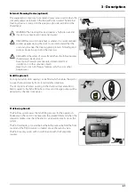
Label for manual steered version (optional)
When having a manually steered model of the sprayer, there is no
hydraulic controls for the steering at hydraulic control unit. So to control
the steering then one of the optional switches (10) on the hydraulic
control unit is used.
•
Place the “Manual steering” label (part no. 72547600) on the
control unit at the sign originally meant for optional function (10).
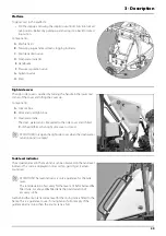
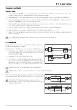
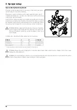
Speed transducer for sprayer
The speed transducer and speed ring are located at the inside of the
sprayers right wheel.
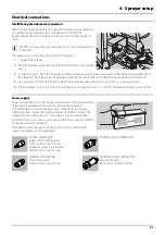
The sensor is an inductive type that requires a metallic protrusion to pass
by it to trigger a signal. To trigger a speed ring is used. It should be
adjusted so transducer is placed to the centre of the holes in the speed
ring (vertical direction). Recommended distance between protrusion
and transducer (A) is 3 to 6 mm. Check this at the entire circumference.
μ
ATTENTION! Correct fitting is indicated by continuous flashing
from transducer when the wheel rotates.
Summary of Contents for NAVIGATOR DELTA
Page 4: ...1 EC Declaration 4 ...
Page 10: ...Table of Contents 10 ...
Page 14: ...2 Safety notes 14 ...
Page 32: ...3 Description 32 ...
Page 54: ...4 Sprayer setup 54 ...
Page 74: ...5 Operation 74 ...
Page 76: ...6 Maintenance 76 Boom lubrication oiling plan ...
Page 104: ...7 Fault finding 104 ...
Page 120: ...HARDI INTERNATIONAL A S Herthadalvej 10 DK 4840 Nørre Alslev DENMARK ...