
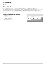


4 - Sprayer setup
31
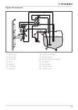
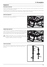
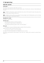
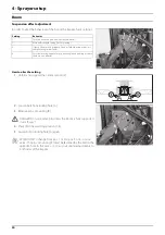
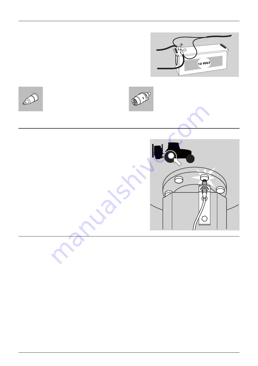
Power supply
Power requirement is 12V DC. Always note polarity! For proper function
of the electric equipment, the wires must have the following
recommended cross sectional areas and correct fuses to ensure a
sufficient power supply. The delivered power connectors follows the
standard of most newer tractors. If you have a tractor with another
power connector, it is necessary to disassemble the connector and fit it
to the actual tractor connector.
The number and the type of connectors may vary on the specific
sprayer, depending on its equipment.
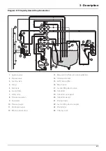
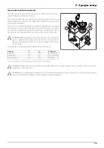
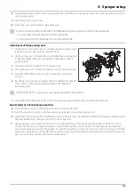
Speed transducer for tractor
For tractors without speedometer. Note the following if the speed
transducer is fitted to the tractor.
The speed transducer and the speed ring should be located at the inside
of the tractor’s right wheel. The sensor is an inductive type that requires
a metallic protrusion (e.g. bolt head) passing by in order to trigger a
signal. It should be adjusted so transducer is placed to the centre of the
holes in the speed ring (vertical direction). Recommended distance
between protrusion and transducer (A) is 3 to 6 mm. Check this in the
entire circumference.
Correct fitting is indicated by constant flashing of the transducer when
the wheel rotates.
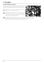
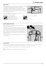
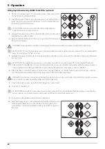
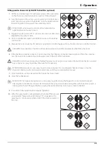
Road safety kit
The sprayer can be equipped with rear lights. Connect the plug for rear lights to the tractor’s 7-pin socket, and check the
function of rear lights, stop lights, side lights and direction indicators on both sides before driving.
The wiring is in accordance with ISO 1724. See section in “Technical specifications”.
μ
ATTENTION! Turn OFF all work lights when driving on public roads!
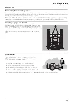
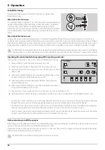
CIGAR CONNECTOR
Spray control unit requires:
Wire 2.5 mm, Fuse 10 Amp
Hydraulic control unit requires:
Wire 4.0 mm, Fuse 16 Amp
TRAFFIC LIGHT CONNECTOR
Summary of Contents for MASTER PRO VHH
Page 6: ...Table of Contents 6 ...
Page 8: ...1 EC Declaration 8 ...
Page 12: ...2 Safety notes 12 ...
Page 50: ...5 Operation 50 ...
Page 52: ...6 Maintenance 52 Boom lubrication oiling plan Lift lubrication oiling plan ...
Page 70: ...7 Fault finding 70 ...
Page 76: ...8 Technical specifications 76 Charts Boom hydraulic Z ...
Page 78: ...8 Technical specifications 78 ...
Page 82: ...HARDI INTERNATIONAL A S Helgeshøj Allé 38 DK 2630 Taastrup DENMARK ...