


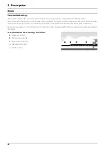

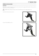

3 - Description
17
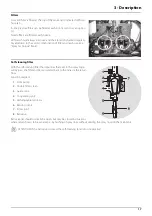
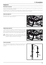
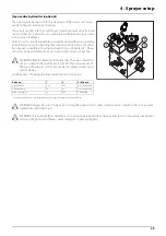
Filters
A suction filter is fitted at the top of the tank and is indicated with red
hose tail.
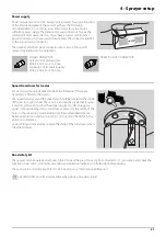
In-line pressure filters can be fitted at each boom section as an option
(J).
Nozzle filters are fitted at each nozzle.
All filters should always be in use and their function checked regularly.
Pay attention to the correct combination of filter and mesh size (see
“Spray Technique” book).
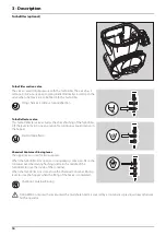
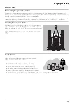
Self-cleaning filter
With the self-cleaning filter the impurities that exist in the spray liquid
will by-pass the filter and be recirculated back to the tank via the return
flow.
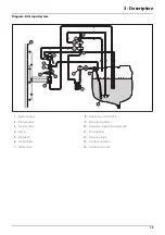
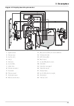
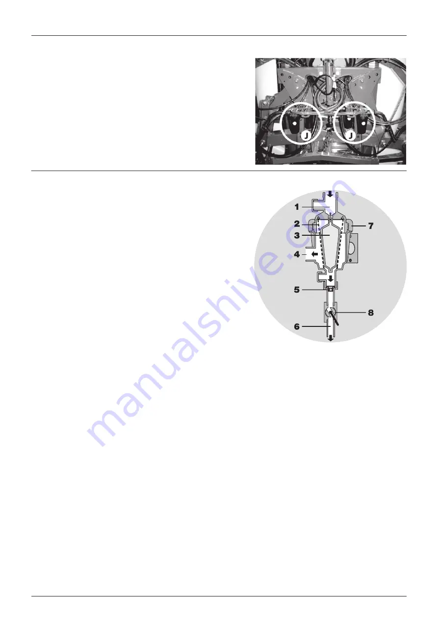
Function diagram
1.
From pump
2.
Double filter screen
3.
Guide cone
4.
To operating unit
5.
Exchangeable restrictor
6.
Return to tank
7.
Screw joint
8.
Ball valve
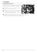
Ball valve (8) should normally be open, but may be closed in situations
where return flow is to be avoided, i.e. by flushing of spray lines without diluting the spray liquid in the main tank.
μ
ATTENTION! If the ball valve is closed, the self-cleaning function is inoperative!
Summary of Contents for MASTER PRO VHH
Page 6: ...Table of Contents 6 ...
Page 8: ...1 EC Declaration 8 ...
Page 12: ...2 Safety notes 12 ...
Page 50: ...5 Operation 50 ...
Page 52: ...6 Maintenance 52 Boom lubrication oiling plan Lift lubrication oiling plan ...
Page 70: ...7 Fault finding 70 ...
Page 76: ...8 Technical specifications 76 Charts Boom hydraulic Z ...
Page 78: ...8 Technical specifications 78 ...
Page 82: ...HARDI INTERNATIONAL A S Helgeshøj Allé 38 DK 2630 Taastrup DENMARK ...