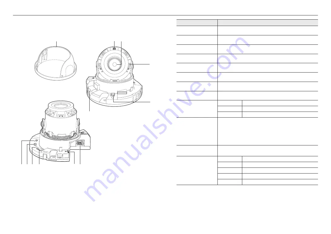
overview
10_
overview
Components
Item
Description
a
Inside cover
Protective cover for the main body.
b
Illumination Sensor
Detects incoming light to control the IR LED.
c
Lens
Lens for the camera.
d
IR LED
These infrared LED’s are controlled by the illumination sensor.
e
Power Port
Port for power terminal block.
f
Microphone hole
Microphone is embedded.
g
Network Port
Used to connect the PoE or Ethernet cable for network connection.
h
Micro SD Card slot
Compartment for the Micro SD card.
i
Alarm I/O Port
ARM-IN
Used to connect the alarm input sensor or external day/night sensor.
ARM-OUT
Used to connect the alarm output signal.
GND
These are common ports to connect alarm input/output signals.
j
Reset Button
The button restores all camera settings to the factory default.
Press and hold for about 5 seconds to reboot the system.
J
If you reset the camera, the network settings will be adjusted so that DHCP can be
enabled. If there is no DHCP server in the network, you must run the Device Manager
program to change the basic network settings such as IP address, Subnet mask,
Gateway, etc., before you can connect to the network.
k
Test monitor out port
Output port for test monitoring the video output. Use the test monitor cable to connect to a
mobile display and check the test video.
l
Zoom/Focus Control Button
T
Zoom in (Tele)
W
Zoom out (Wide)
N
Focusing on a near object (Near)
F
Focusing on a far object (Far)
Focus Control
Press this button for automatic focus control.
a
NETWORK
ACT
LINK
DC 12V
RESET
1 ALARM IN
2 ALARM OUT
e
d
c
b
f
VIDEO
RESET
1 ALARM IN
2 ALARM OUT
1 2 3 4 5 6 7 GND
T
W
AF
N
F
lkj i
hg
Summary of Contents for QND-7022R
Page 40: ......


