28
Caution
Normally only one rocker operation is required to trigger the motor sequence detection. If the rocker position
is operated incorrectly, you need to repeat step 2 to trigger the detection.
Direction test
:
After unlocking, the aircraft propellers rotate at a low and constant speed (if there is no operation, the power
output will be turned off within 3 seconds). Operate the four channels of the remote controller to determine
whether the forward whether the rotation direction is correct. For example, when the propeller is rotated at the
lowest speed, Push up the "forward rocker", and the two propellers on the back side of the aircraft will rotate, and
the propellers on the front side will stop. In the same way, when the roll rocker is pushed to the left, the propellers
on the left side will stop and the propellers on the right side will rotate.
3.2
Charge
Note
If the remaining power is sufficient, you do not need to perform the following sections.
3.2.1
Charge the Aircraft Battery
The connection of the smart battery and charger is shown below.
Figure 3-22
Instructions:
1.
Before connecting the 220V power supply, place the switch in the OFF position (0). At this time, the external
power supply channel is cut off and the charger does not work.
2.
After connecting the 220V power supply, place the switch in the I position to open the external power supply
channel. The battery indicator L0 is lit and the internal fan starts to rotate. At this time, the charging channel is
closed.
3.
Connect the battery's wiring to the output port and the equalizer port. The charging channel will be opened, the
battery charging progress bar will be wave-type flashing, the battery indicator light will be bright red, the internal
and external fans will rotate at the same time, and it will enter the charging state.When the battery indicator is full
and constant, charging is complete.
4.
During the charging process, press the start button to exit the charge mode. If any abnormality occurs, press the
start button to exit the exception.
Summary of Contents for 3WD4-QF-10B
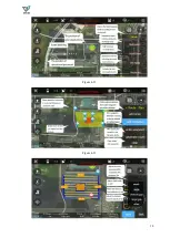
Page 20: ...19 Figure 3 3 Figure 3 4 Figure 3 5 ...
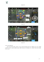
Page 21: ...20 Figure 3 6 Figure 3 7 Figure 3 8 ...
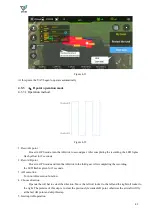
Page 22: ...21 Figure 3 9 Figure 3 10 Figure 3 11 ...
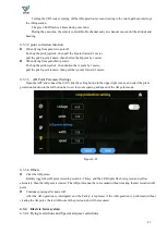
Page 32: ...31 Figure 3 25 ...
Page 39: ...38 Figure 4 11 Figure 4 12 ...


