background image

41

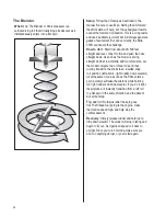
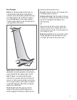
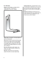
The Elevator

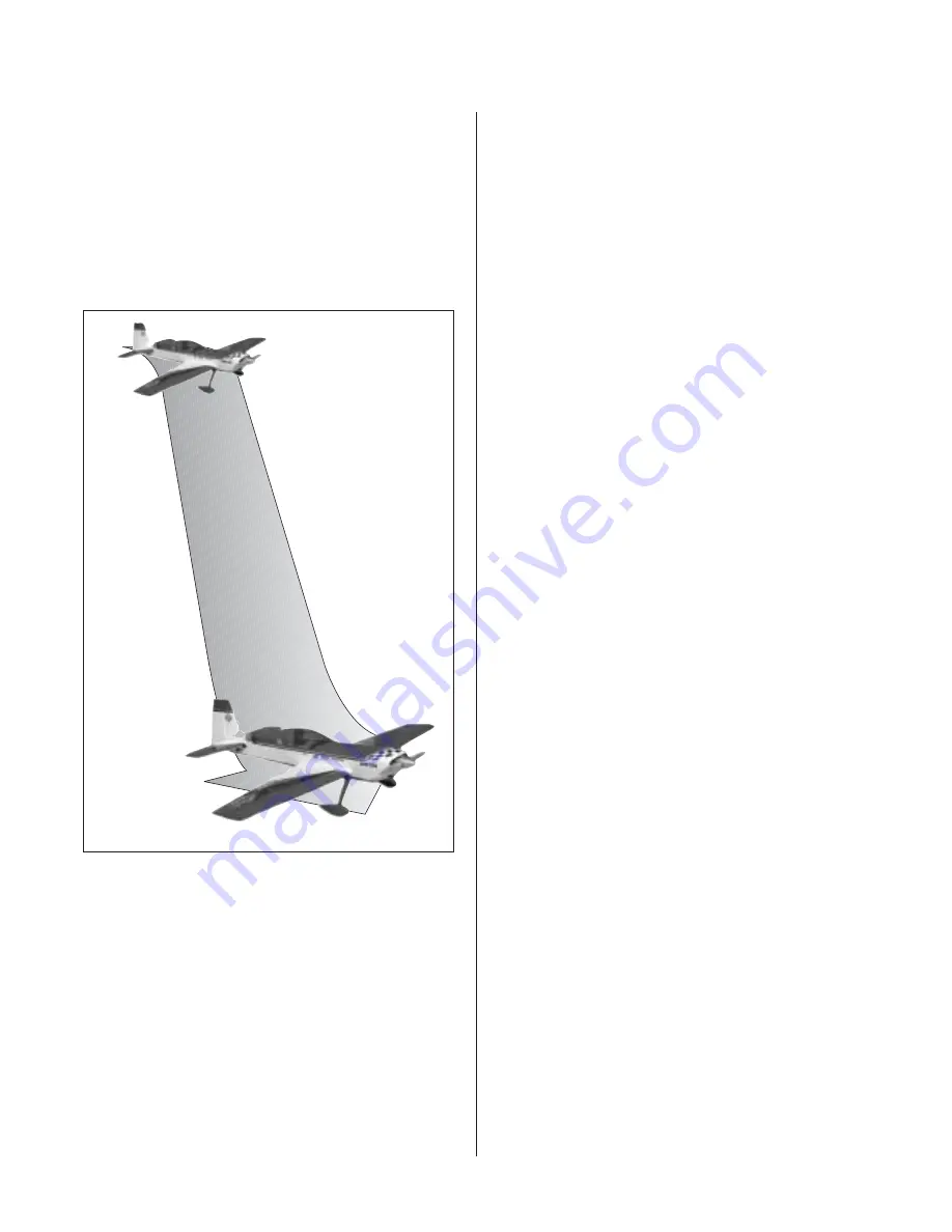
What it is

: The plane drops vertically while in a

nose high attitude. Depending on the head wind
conditions, the model will drop anywhere from about
a 45-degree angle in calm conditions to vertical or
even a little backwards in more windy conditions.
Throttle is used to determine rate of descent and the
nose high attitude of the model.

Setup

: Same as the Blender, only for this one, flip

the switch to turn on the spoilerons. This will help to
keep the Extra 330S from teetering back and forth.

How it’s done

: At near stall airspeed up high,

slowly feed in up elevator until you have the full 3D
rate up in it. With low throttle, the Extra will fall like a
rock. To guide it around, use the rudder, not ailerons.
Just keep the wings level. Add power to change the
attitude of your Extra 330S.

Trickiest part

: Aside from steering it with the

rudder, you’ll quickly see that this maneuver is a
matter of juggling the throttle and rudder to get the

plane to go where you want it to go.

Recovery

: Basic recovering—add full power, flip to

normal rate elevator, and fly out. 

Advanced Recovery

: Take the elevator all the way

to the ground—adding some power before it touches
down to slow the descent and transition into a
Harrier and land.

OR

Add power to get the nose to rise to vertical and
transition into a torque roll. Elevator down from a
hundred feet down to 20 feet (or less) and power up
into a torque roll. Ooh!!

Worst way to mess up

: Let your direction control

(rudder) get away from you after starting too low—
you could snap it right into the ground. Ouch!

Summary of Contents for Extra 330S

Page 1: ...b 11 2 kg 11 5 kg Radio 4 channel w 9 servos Engines 3 8 4 8 cu in Extra 330S WE GET PEOPLE FLYING TM Superior controllability and aerobatic flight characteristics Lightweight construction Designed by veteran TOC competitor Mike McConville 90 built 1 3 scale ARF Plug in wings and stabilizers for easy transport and field assembly ...

Page 2: ...Section 7 Rudder and Elevator Servo Installation 17 Section 8 Elevator Linkage Installation 18 Section 9 Rudder Linkage Installation 21 Section 10 Landing Gear Installation 24 Section 11 Wheel Pant Installation 25 Section 12 Tail Wheel Installation 27 Section 13 Receiver Battery and Fuel Tank Installation 28 Section 14 Mounting the Engine and Cowl 30 Section 15 Hatch Assembly 33 Section 16 Balanci...

Page 3: ... for throttle JRPS537 recommended or equivalent 8 hi torque servos JRPS8411 recommended or equivalent Recommended JR Systems PCM10X XP8103 X 378 XP662 XF631 XF421 Quattro Recommended Engines G 62 GT 80 JR XP8103 JR PCM 10X Zenoah GT 80 ZENE80T Zenoah G62 ZENE62A A B C D E Other Items Needed not included in the kit Propeller consult engine instructions 12 Servo Extension JRPA098 18 Servo Extensions...

Page 4: ...ushes Felt tipped pen or pencil File Measuring device e g ruler tape measure Mixing sticks for epoxy Paper towels Petroleum jelly Rubbing alcohol Sanding bar Sandpaper coarse Clear UltraCote HANU964 Covering Iron HAN101 Dental floss or string Optional Hangar 9 1 3 Scale Hardware Package HAN1220 JR HAN1221 Futaba Tail Wheel Assembly with Hardware OHI130 4 40 1 2 3D arm 11 4 Futaba 2 HAN3579 4 40 Ba...

Page 5: ...e of the final user assembled product By the act of using the product the user accepts all resulting liability Once assembly of the model has been started you must contact Horizon Hobby Inc directly regarding any warranty question that you have Please do not contact your local hobby shop regarding warranty issues even if that is where you purchased it This will enable Horizon to better answer your...

Page 6: ...uded with the servo Step 2 Plug a 12 and a 24 servo extension onto two of the servos Either tie the servo leads together using a commercially available connector or use unwaxed dental floss to secure the extensions to prevent them from coming loose during flight Step 3 Tie a weight to a piece of string A wheel collar works great in this application Lower the string into the wing from the aileron s...

Page 7: ...sition the servo so the output shaft is towards the trailing edge of the wing Use a 1 16 drill bit to drill the locations for the servo screws Mount the servos using the hardware provided with the servos Step 5 Repeat Steps 3 and 4 for the servo near the root of the wing panel Step 6 Repeat Steps 1 through 5 for the remaining wing panel Photo for Step 4 Photo for Step 4 ...

Page 8: ...ron hinge bevel Step 2 Measure exactly 3 3 8 forward from the trailing edge of the aileron and make another mark using a felt tipped pen The intersection of the line from Step 1 and this line will be the position for the control horn Step 3 Repeat Steps 1 and 2 for the second control horn location Step 4 Remove the ailerons from the wing Use rubbing alcohol to remove any tape residue Step 5 Using ...

Page 9: ... amount of 30 minute epoxy and lightly coat the inside of the tapped hole and the 8 32 x 2 Hangar 9 control horn screw From the top of the aileron screw the 8 32 x 2 into the tapped hole and securely tighten Wipe away any excess epoxy with rubbing alcohol and a paper towel Screw the A nut in place as shown Allow the epoxy to fully cure Step 8 Screw the molded swivel link onto the 8 32 screw until ...

Page 10: ... point hinge using coarse sandpaper This will improve the bond of the epoxy to the hinge Step 2 Mix 1 ounce of 30 minute epoxy Using a glue syringe or toothpick place a sufficient amount of 30 minute epoxy into one of the hinge pockets in the aileron leading edge Install one of the hinge points until the hinge pin center is flush with the leading edge of the aileron Some epoxy should ooze out of t...

Page 11: ... syringe or toothpick place a sufficient amount of epoxy in each of the hinge pockets in one wing panel Step 5 Carefully attach the aileron to the wing making sure the hinges are inserted in their respective hinge pockets Press the aileron and wing together such that less than a 1 64 hinge line gap exists between the aileron and wing The bevels should virtually touch Use a paper towel and rubbing ...

Page 12: ... the fold Required Parts Wing panel right and left Aileron left and right Required Tools and Adhesives Straight edge ruler Felt tipped pen Scissors Hobby knife w 11 blade Clear UltraCote HANU964 Covering Iron HAN101 It s imperative that the aileron and elevator hinge lines be sealed airtight to prevent flutter Sealing the hinge line has several advantages A sealed hinge line gives a greater contro...

Page 13: ...Step 5 Remove the backing from the UltraCote Place the folded crease side into the center of the hinge line on the bottom of the wing Using a straight edge as shown hold one side of the covering in place while ironing down the opposite side with a sealing iron We recommend setting the iron temperature to 320 for this procedure Step 6 Fully deflect the aileron in the up position Place the straight ...

Page 14: ...inkage Adjust the linkage length until the hole in the ball link aligns with the outer hole in the servo arm when the aileron is neutral and the servo arm is centered Note Hangar 9 Titanium Pro Links feature right hand threads on one end and left hand threads on the other allowing for easy accurate adjustment without disconnecting the linkages Consistently putting the right hand threads toward the...

Page 15: ...kage to the servo horn on the aileron Adjust the link so the aileron is centered at the same time as the servo Step 5 Repeat Steps 1 through 4 for the second servo Step 6 Repeat Steps 1 through 5 for the remaining servos in the opposite wing panel Photo for Step 4 ...

Page 16: ...and reinstall the pin Locate the wing tube and carefully slide it into one wing panel Slide the wing with tube into the wing tube opening in the fuselage Make sure the wing panel anti rotation pins slide into the holes provided in the fuselage Note It may be necessary to slightly enlarge the holes in the fuselage for the anti rotation pins using a small round file Step 2 Carefully slide the remain...

Page 17: ...o install four 18 servo extensions one on each servo Either tie the servo leads together using a commercially available connector or use unwaxed dental floss to secure the extensions to prevent them from coming loose during flight Install one side only of the two Y harnesses to two of the servos also tying knots to prevent disconnection The other two servos will be hooked up to the Y harness when ...

Page 18: ...the above marked position It s important to drill 90 to the top of the elevator Be especially careful when penetrating through the bottom surface of the elevator as it s easy to split out the wood and rip the covering Placing a wooden block under the elevator and drilling slowly will prevent these problems If you choose to use the counter sink screws included counter sink the top of the elevator t...

Page 19: ...he ailerons The shortened hinges will be installed into the stabilizer towards the root After hinging the elevator use the same technique to seal the elevator s hinge gaps Use Clear UltraCote for the bottom of the elevator Step 8 Insert the longer tube into the aft hole in the fuselage Measure the distance of the exposed tube and adjust until both side are equal Step 9 Mark the tube on both side o...

Page 20: ...tall the shorter tube into the stabilizer half with the secured tube Slide the assembly into the fuselage Slide the remaining stab half onto the tubes and drill and tap the location for the 4 40 retaining bolt Install the bolt to complete the procedure Step 12 Remove the stock servo arms from the elevator servos and replace them with heavy duty 1 arms The arms need to face down as shown Be sure to...

Page 21: ...luded in the Hangar 9 package attach the ball link to the outer hole in the arm The correct sequence is 4 40 screw ball link standoff servo arm and 4 40 nut Be sure to use threadlock Section 9 Rudder Linkage Installation Required Parts Rudder Fuselage assembly Required Tools and Adhesives 8 32 tap Drill Bit 5 32 Drill Tap handle Thick CA Rotary tool Cut off wheel Ruler 4 40 linkage Note The elevat...

Page 22: ...t off wheel to remove the head of the 4 bolt Step 5 Measure and mark the center of the bolt Step 6 Measure the width of the rudder Divide the measurement by 2 and make marks on either side of the center mark the distance calculated Step 7 Apply a few drops of thick CA on the bolt at the center This will secure the bolt and prevent it from loosening during flight Install the bolt using the lines dr...

Page 23: ...a 4 40 ball link 5 to 6 turns onto a 5 long 4 40 linkage Screw the opposite end of the linkage into the swivel control horn that was installed in Section 6 Adjust the length until the hole in the ball link lines up with the outer hole in the servo arm when the rudder is at neutral and the arm is centered Step 13 Using the 4 40 screws and nuts included in the Hangar 9 package attach the ball link t...

Page 24: ...re the axles using an adjustable wrench and the nuts provided with the axles Step 2 Install the landing gear using four 10 32 x 1 socket head bolts four 10 lock washers and four 10 32 nylon lock nuts The lock nuts are placed inside the fuselage Step 3 Press the landing gear fairing into position to transfer the location of the bolt heads into the foam Use a hobby knife to remove the foam to provid...

Page 25: ...ou are marking the side that has the plywood reinforcement Step 2 Place the pant on a flat surface and use a square to draw a 11 2 line through the mark made in the previous step Mark the wheel pant 3 4 from the surface for the location of the axle Step 3 Use a rotary tool or drill to make a 1 2 hole at the location made in the last step Note When using drill bits it is best to start small and wor...

Page 26: ...nother 3 16 wheel collar It will be necessary to fit the parts inside the wheel pant and slide them onto the axle Note It may be necessary to drill the hole in the wheel to fit onto the axle Step 7 Secure the pant in place using a 4 40 x 1 2 socket head screw 4 lock washer and 4 washer Use threadlock on the screw to prevent it from coming loose in flight Step 8 Center the wheel in the wheel pant a...

Page 27: ...fuselage Using a felt tipped pen mark the positions for the mounting screws through the tail wheel bracket Step 3 Remove the bracket and drill 3 32 pilot holes at the previously marked positions Step 4 Use two 6 x 3 4 sheet metal screws to secure the tail wheel bracket in place A hardwood plate is positioned in the rear of the fuselage allowing these screws to be firmly tightened Hint Remove the 6...

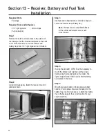
Page 28: ...ep 3 Use foam and rubber bands or Velcro straps to secure the receiver to the battery tray Note We have also mounted MatchBoxes for the rudder and elevator servos next to the receiver Step 4 If using the Zenoah GT80 it will be necessary to mount the battery pack slightly near the wing s trailing edge to properly balance the model The lighter weight Zenoah G62 requires that the battery be mounted i...

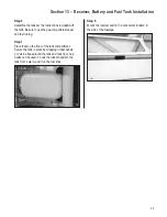
Page 29: ... stopper and fuel tubing Step 7 Place foam on the floor of the tank compartment Secure the tank in place by wrapping rubber bands or Velcro straps around the tank and tank floor Cup hooks can be used to hook the rubber bands to the tank floor Later we will run the fuel lines Step 8 Mount the receiver switch in a convenient location in the side of the fuselage ...

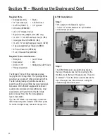
Page 30: ...GT80s The G62 offers good sport performance and is a good choice for doing all IMAC basic and sportsman maneuvers While the G62 equipped Extra doesn t quite provide unlimited vertical performance most experienced sport flyers find that the G62 offers plenty of power for all but the most aggressive types of aerobatics If you re a 3D fanatic or an Advanced or Unlimited IMAC class competitor Zenoah s...

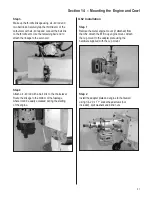
Page 31: ...ch a 4 40 rod with a ball link to the choke lever Route the linkage to the bottom of the fuselage where it can be easily accessed during the starting of the engine G62 Installation Step 1 Remove the metal engine mount if attached from the G62 Attach the B B Cup engine mount Attach the cup mount to the adapter plate using the hardware supplied with the cup mount Step 2 Install the adapter plate and...

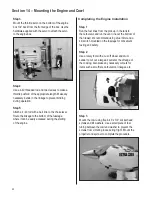
Page 32: ...e starting of the engine Completing the Engine Installation Step 1 Run the fuel lines from the pick up in the tank to the carburetor and run the vent line out the bottom of the firewall We recommend using a fuel filter and a kill switch mounted on the fuselage for convenient fueling and safety Step 2 Use a rotary tool with a cut off wheel and drum sander to cut out a large air outlet at the aft ed...

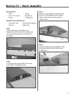
Page 33: ...ld on with four 4 40 socket head cap screws Remove these and lift the hatch from the fuselage Step 2 Cut out the instrument panel decal from the decal sheet Attach it to the hatch as shown Step 3 Install a 1 3 scale pilot figure to the hatch using Shoo Goo or similar adhesive that will remain flexible Let the glue dry before securing the canopy in place Step 4 Position the canopy onto the canopy h...

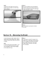
Page 34: ...ctly balancing an aerobatic model is critical to its performance and flight characteristics Checking the balance on giant scale models is best done with two people Step 1 On the top of the wing tips measure back 41 2 and 53 4 from the leading edge and mark both places with a felt tipped pen This is the recommended center of gravity CG range Step 2 Fully assemble the model With a helper lift the ai...

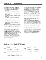
Page 35: ...e necessary to Y harness the two rudder and elevator servos a reversed elevator servo is needed to achieve the correct control direction A servo reverser can be used here Special attention must be taken with the rudder servos so that they don t fight each other throughout the rudder travel This is caused by nonsymmetrical pushrod geometry from right to left It may be necessary to rotate the arm on...

Page 36: ...hile many smaller models are very tolerant of improper control linkage setups and flying techniques large models are not Don t let that scare you away from large models they are truly one of the best flying experiences in RC that money can buy However please pay particular attention to the following areas Seal the aileron and elevator hinge gaps This should be considered part of finishing the mode...

Page 37: ...0 turns at approximately 7000 rpm and a preshaped and balanced Bolly 24 x 10 at 7700 rpm Both work well but I feel the preshaped prop has the edge in hovering maneuvers This combination has proven to be totally unlimited and allows anything imaginable from torque rolls just a few inches off the ground to multiple vertical snaps I found that adequate engine cooling is very important with the GT80 a...

Page 38: ...ponse less sensitive in the rpm ranges used for hovering the model This makes altitude control easier and smoother when doing torque rolls Rates and Expos when and where to use them I always use Expo to soften the feel of the model On high 3D rates I use quite a bit The goal on 3D rates is to get the model to feel the same around neutral as it does on low rates I use low rate settings for all flyi...

Page 39: ... at its Best 3D maneuvers in simplest terms are maneuvers performed by an airplane that are not usually done in a normal airplane flight path What can be done with a 3D capable plane is to make it fly like no other For example hovering in the air nose high at a 45 degree descent floating along in level flight hanging on the prop or tumble tail over nose in a rapid flipping motion When you sprinkle...

Page 40: ...ottle add full left aileron Let the model compete two or three rolls and then quickly transition the sticks to an inverted snap roll position left aileron right rudder down elevator all at the same time As soon as the Extra enters a spin quickly neutralize the ailerons while holding full right rudder and down elevator If you do it right the airplane will instantly transition from a left roll to a ...

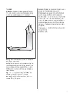
Page 41: ...guide it around use the rudder not ailerons Just keep the wings level Add power to change the attitude of your Extra 330S Trickiest part Aside from steering it with the rudder you ll quickly see that this maneuver is a matter of juggling the throttle and rudder to get the plane to go where you want it to go Recovery Basic recovering add full power flip to normal rate elevator and fly out Advanced ...

Page 42: ... the model In a head wind you may also have to juggle the elevator some to keep the model from pitching up to a vertical attitude Use the rudder to steer the model around in the Harrier attitude Try to use the ailerons very little as they will cause the model to wobble side to side Trickiest Part Keeping up with the model if it begins to wobble Recovery Simply add full power and reduce elevator to...

Page 43: ... a vertical position Add throttle to keep the nose pointed up and make corrections with rudder and elevator to keep things straight If the model hovers but won t start rolling left quickly blip the throttle up and down The torque change will usually get it going Trickiest part Recognizing your correction when the model s belly is toward you Tip Think push the rudder toward the low wing when the be...

Page 44: ...instantly transition from a vertical dive to an Elevator Tip Add a little throttle just after transition to an Elevator That ll keep fuel going to the engine and keep it from quitting Recovery Simply add full power and reduce elevator to transition into normal forward flight Advanced Recovery Juggle the throttle to slowly lose altitude and do a Harrier landing The model will land on the rear of th...

Page 45: ...eed and add power at the same time that you begin to pull full up elevator Recovery Simply release the elevator go to full throttle and fly out upward Advanced Recovery Juggle the throttle to sustain a hover and transition into a torque roll Worst way to mess up Don t get the throttle in quickly enough and the model falls backward Great combo This has become one of my favorites to do with the Extr...

Page 46: ...xplosive bombs dropped from models smoke bombs all explosive gases such as hydrogen filled balloons ground mounted devices launching a projectile The only exceptions permitted are rockets flown in accordance with the National Model Rocketry Safety Code or those permanently attached as per JATO use also those items authorized for Air Show Team use as defined by AST Advisory Committee document avail...

Page 47: ...e exception of events flown under AMA Competition rules after launch except for pilots or helpers being used no powered model may be flown closer than 25 feet to any person 9 Under no circumstances may a pilot or other person touch a powered model in flight Organized RC Racing Event 10 An RC racing event whether or not an AMA Rule Book event is one in which model aircraft compete in flight over a ...

Page 48: ... 6061 2003 Horizon Hobby Inc 4105 Fieldstone Road Champaign Illinois 61822 877 504 0233 www horizonhobby com WE GET PEOPLE FLYING TM ...

Reviews: