18
Section 8 – Elevator Linkage Installation
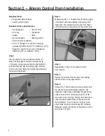
Required Parts
• Fuselage
• Short stabilizer tube
• Long stabilizer tube
• Stabilizer half (left and right)
Required Tools and Adhesives
• 4-40 tap
• Drill
• #4 lock washer (2)
• Clear UltraCote®
• Drill bit: #43 or 3/32" (for 4-40 tap)
• 4-40 x 1/2" socket head bolt (2)
• Aluminum servo arms (2)
• Control horn ball ends (2)
• 4
1
/
2
" 4-40 linkage (2)
The technique for installing the control horns in
the elevators is similar to the aileron control
horn installation.
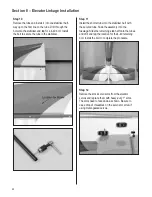
Step 1
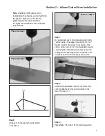
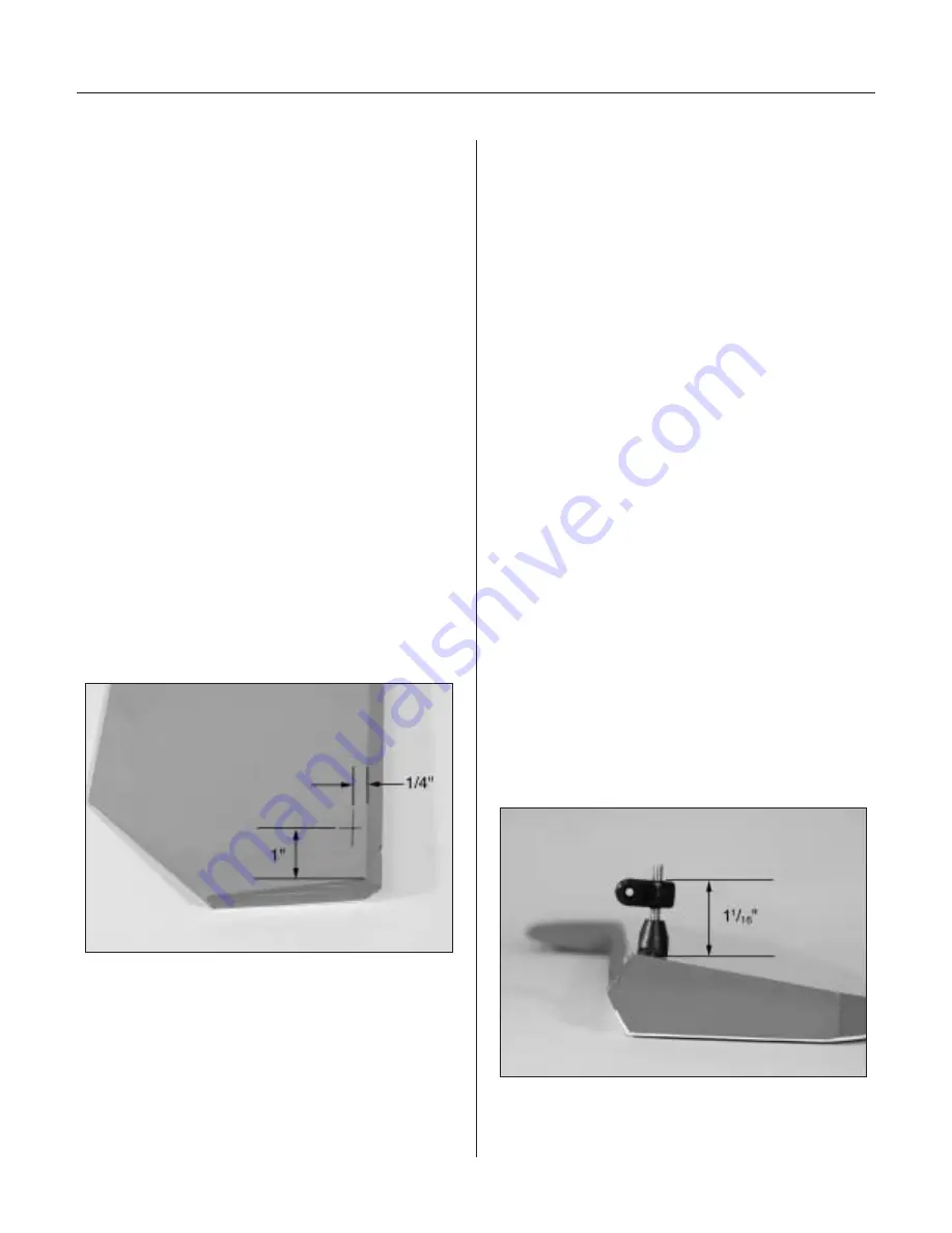
To properly locate the position of the control horn
on the bottom of the elevator, measure inward 1"
from the root and rearward 1/4" from the top of
the bevel. Mark this position on both elevators.
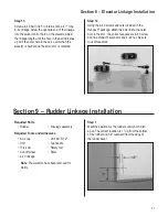
Step 2
Using a 5/32" drill bit and drill press, carefully drill
through the elevators at the above marked position.
It’s important to drill 90° to the top of the elevator.
Be especially careful when penetrating through the
bottom surface of the elevator, as it’s easy to split
out the wood and rip the covering. Placing a wooden
block under the elevator and drilling slowly will
prevent these problems. If you choose to use the
counter sink screws included, counter sink the
top of the elevator to allow the screws to fit flush.
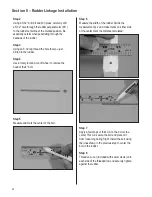
Step 3
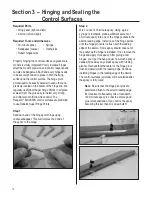
Using an 8-32 tap, thread the holes just drilled
in the elevators.
Step 4
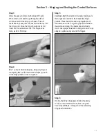
Mix a small amount of 30-minute epoxy and lightly
coat the inside of the threaded holes and the
8-32 x 2" Hangar 9
®
screw. From the top of the
elevator, thread the 8-32 screws into the tapped
holes and tighten. Wipe away any excess epoxy
with rubbing alcohol and paper towels.
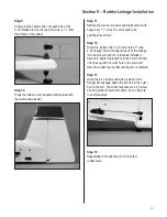
Step 5
Screw the molded swivel link onto the 8-32 screw
until the distance from the elevator surface to
the bottom of the link is 1
1
/
16
". Repeat this for
the other elevator.

