
14
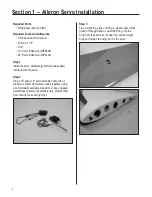
Section 5 – Aileron Linkage Installation
Required Parts
• Aluminum servo arms (4)
• Control horn ball ends (4)
• 4
1
/
2
" 4-40 linkage (4)
Required Tools and Adhesives
• Phillips screwdriver (small)
• Threadlock
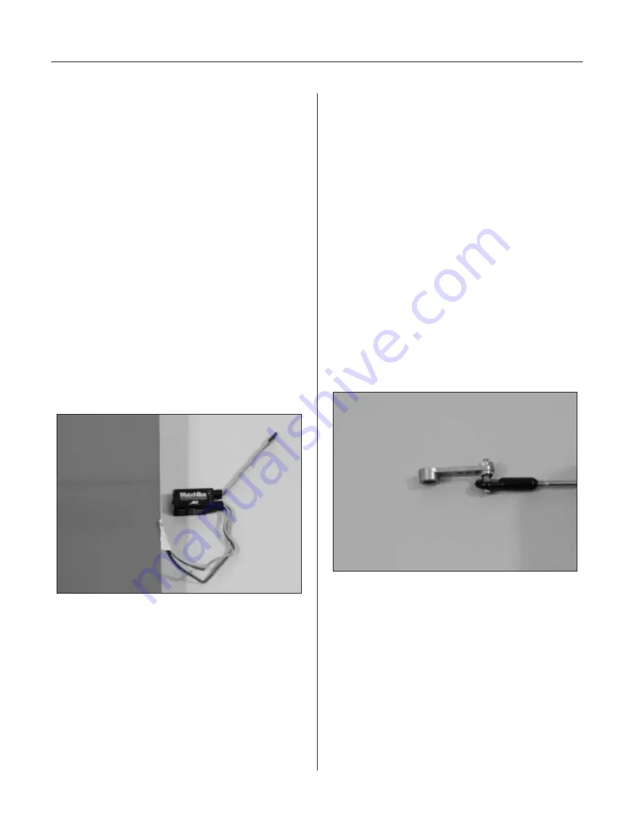
MatchBox Option:
To simplify the installation of
the aileron servo linkages, you may want to use the
JR™ MatchBox™ servo matching/power system
(JRPA900). Four MatchBoxes would be used in this
application—one for each wing panel, one for the
rudder and one for the elevator servo configuration.
The MatchBox allows easy adjustment of the servo’s
center and endpoints, making radio setup a snap.
You can also use a separate battery to run the
Matchbox, reducing the load on the flight battery
powering the receiver.
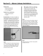
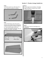
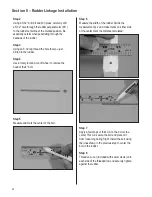
Step 1
Screw a 4-40 ball link 5 to 6 turns onto each end of
a 4
1
/
2
" long 4-40 linkage. Adjust the linkage length
until the hole in the ball link aligns with the outer
hole in the servo arm when the aileron is neutral
and the servo arm is centered.
Note
: Hangar 9
®
Titanium Pro-Links feature
right-hand threads on one end and left- hand
threads on the other, allowing for easy,
accurate adjustment without disconnecting
the linkages. Consistently putting the right-
hand threads toward the servo arms on all
servos will prevent you from getting confused
as to which way to turn the linkage to lengthen
or shorten the link. Hangar 9 also offers a
Pro-Link™ Wrench (HAN3558) to make
adjustments easier.
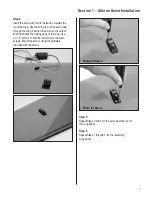
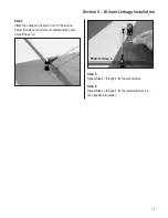
Step 2
Using the 4-40 screws (don’t substitute a standard
screw) and nuts included in the Hangar 9 package,
attach the ball link to the outer hole in the arm from
the bottom side as shown. The sequence is screw,
tapered standoff, ball link, servo arm and nut. Don’t
forget to use threadlock.
Step 3
Attach the servo horn to the servo using the screw
provided with the servo.


