13
35% Extra 300 ARF Assembly Manual
13. Apply a drop of threadlock to the servo center
screw and tighten the screw. This is the outer hole in the JR
Aluminum arm.
14. Tighten the servo arm setscrews. Move the servo
arm all the way to the front and back to access the mounting
lugs.
15. Connect the ball link to 1 1/2-inch servo arm. In
case of JR Aluminum servo arm, this is the outermost hole.
Insert the ball link screw into the ball link through the conical
spacer (flat surface facing the arm) and servo arm and then
nut.
16. With servo arm perpendicular to the center line
of the stab, use a Hangar 9 Pro-Link Wrench to adjust the
linkage so the elevator is at neutral position.
Rudder Installation
Required Parts
Fuselage
Rudder
Hinge rod
Required Tools and Adhesives
Drill
Pliers
Petroleum Jelly/Industrial lubricant
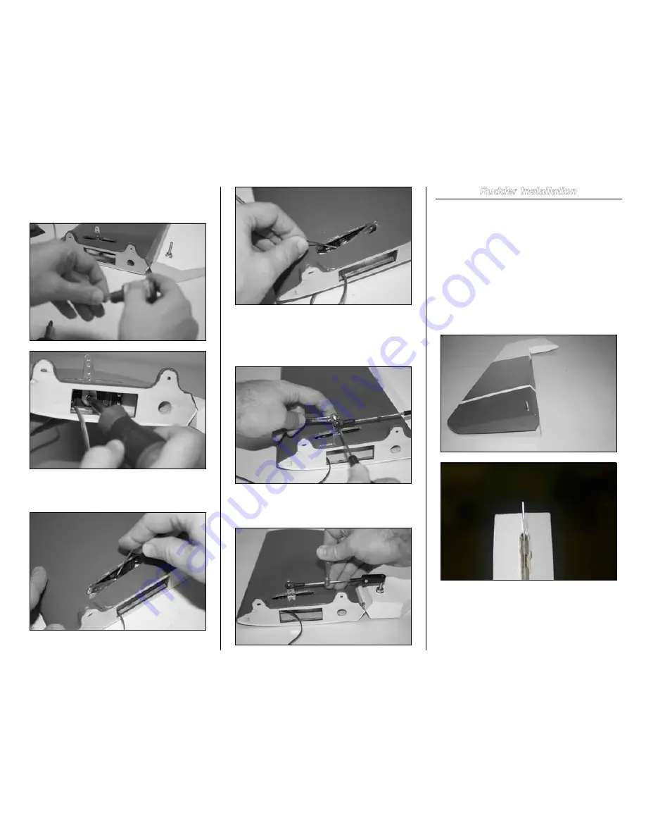
1. Apply some industrial lubricant to the rod. Pass the
rod through the hinges in the rudder and fuselage vertical fin
separately. This helps remove any possible dirt in the hinges
and makes for easier final assembly.
2. Mate the rudder and fuselage vertical stabilizer
and carefully pass the rod through hinges. This can be
accomplished by two ways. 1. Use a drill on slow speed
and gently pass through the rod. If there is any resistance,
back out and repeat. 2. Use a pair of pliers and push the rod
through the hinges. Make sure not to buckle the rod. This is
a rather slow process and needs attention.


