GB
65
480
Tilluftsstos Ø64
1025
2000
Brännbart tak
513
452
189
Tilluftsstos Ø64
Hål i gjuten fotplatta Ø115
A 956
B 865
D 189
C 60
E 103
F 134
Utv. Ø150
392
Brännbar vägg
150
745
817
289
Brännbar vägg
100
450
400
300
100
300
200
100
690
Tillåtet område för
brännbart material
292
Brandmur
50
645
676
239
Brandmur
50*
50
290
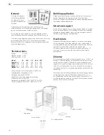
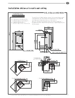
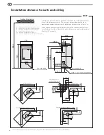
Installation distance to walls and ceiling
Position the stove on a hearth plate and check that the installation distances given
in the diagrams are met. The minimum distance between the stove opening and
combustible parts of the building or décor must be at least 1 m.
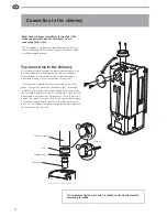
When top connecting a steel flue please refer to the relevant manufacturer’s
installation instructions. Observe the safety distances to combustible material that
steel flues require.
H31, H31A och H32 H32A
* To prevent the discolouring of painted fire walls, we recommend a side distance the same as for the combustible wall.
A = height from floor to chimney connection
B = height from floor to c/c smoke outlet rear
C = distance from back to smoke outlet rear
D = height from floor to air inlet
E= distance from back to c/c air inlet
F=
distance from back to c/c hole in cast foot plate
Combustible ceiling
Combustible wall
Fire-retardant wall of brick or concrete
Permitted area for
combustible material
.
Combustible wall
Fire-retardant wall of brick or concrete
Air inlet Ø64
Hole in cast foot plate Ø115
Air inlet Ø64

