


GB
64
Eldstadsbeklädnad
Rosterreglage
Asklåda
Förbränningsluftsreglage
Brasbegränsare
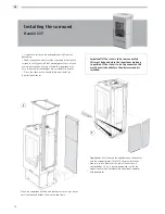
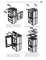
General
This manual contains
instructions about how
the Handöl 30 series
must be assembled and
installed.
To guarantee the function and safety of the stove we
recommend that it is installed by a professional. Our Handöl
agents can recommend a suitable installer.
Instructions for lighting and use are also supplied with the
stove. Read them carefully and keep them safe for future use.
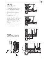
The stove is type approved and must be connected to a chimney
dimensioned for at least 350°C, the external connection
diameter is Ø150 mm. Supply air from the open air should be
used as combustion air.
Building application
Before installing a stove or erecting a chimney it is necessary
for you to apply for planning permission from your local
authority. Ask your local authority for advice regarding building
regulations and the application.
Structural support
Check that the wood joists are strong enough to bear the weight
of the stove and chimney. The stove and chimney can usually be
placed on a normal wooden joist in a single occupancy house if
the total weight does not exceed 400 kg.
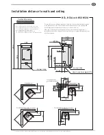
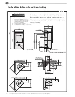
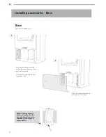
Hearth plate
To protect the floor from any embers the stove must be placed
on a hearth plate. If the floor under the stove is flammable, it
must be protected by a non-flammable material which covers at
least 300 mm to the front and 100 mm on each side.
The hearth plate can consist of natural stone, concrete or 0.7
mm metal. As an accessory, the hearth plate is available in
painted steel.
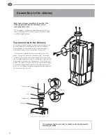
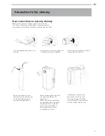
Chimney
The stove requires a draft in the chimney of at least –12 Pa. The
draught is affected both by the length and area of the chimney,
and by how well sealed it is. Minimum recommended chimney
length is 3.5 m and a suitable cross section area is 150-200 cm²
(140-160 mm in diameter). Carefully check that the chimney is
sealed and that there is no leakage around soot hatches and flue
connections.
Note that a flue with sharp bends and horizontal routing reduces
the draught in the chimney. Maximum horizontal flue is 1 m,
on the condition that the vertical flue length is at least 5 m. It
must be possible to sweep the full length of the flue and the soot
hatches must be easily accessible.
t
ANVISNING
31 31A 32 32A 33T
installations
Installationsanvisn
ing 2
Installasjonsanvisning
xx
Installationsanleitung x
x
Installation instruction
xx
eldnings
instruktion
H
30
Eldningsinstruktion 2
Heizinstruktionen 5
Fyringsinstruksjon 9
Lighting Instructions
13
Fyringsvejledning 17
Instructions d’allumage
21
Lämmity sohjeet
25
Istruzioni per l’accensione 28
Stookinstructies
32
HANDÖL
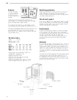
Technical data
Output
3-7
kW
Nominal output
5 kW
Efficiency level
80%
Model 31
31A
32
32A
33T
Weight
(kg) 128 128 128 128 250
Width
(mm) 480 480 480 480 550
Depth
(mm) 450 450 450 450 460
Height
(mm) 1025 1025 1025 1025 1080
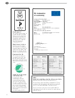
The connection’s external diameter is Ø150 mm.
Type approved in accordance with:
European standard EN-13240
Swedish environmental and quality marking,
P-marking cert. no. 0112/07
Norwegian standard NS 3059, SINTEF 110-0275
German standard DIN 18.891, RRF-40 07 13 90
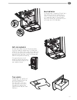
Fire-box surround
Grate shuttle
Ash-pan
Log guard
Air supply control
Type plate