


GB
63
TABLE OF CONTENTS
General 64
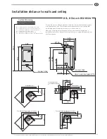
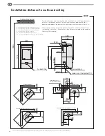
Installation distance to walls and ceiling
65
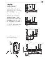
Supply of combustion air
67
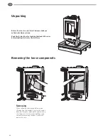
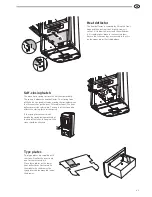
Removing the loose components
68
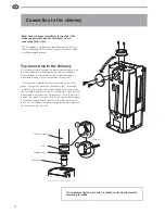
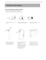
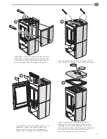
Connection to the chimney
70
Installing the surround, H31/31A/H32/H32A
72
Installing the surround, H33T
74
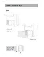
Installing accessories · Base
76
Installing accessories · Drawer
77
Installing accessries · Wood compartment
79
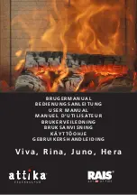
DEAR HANDÖL OWNER
We welcome you to the Handöl family and hope that you will
gain much pleasure from your stove. We understand that you
place high demands on both quality and design. As a new
owner of a stove from Handöl you have a stove with timeless
design and a long lifetime.
The stove combustion is also environmentally friendly and
efficient for the best heat production.
Read the installation instructions carefully before you begin
installation and the separate lighting and user instructions
before you light the fire.
WARNING!
The stove becomes very hot when lit
During operation, certain surfaces of the stove
become very hot and can cause burn injury if
touched. Be aware of the strong heat radiated
through the hatch glass. Placing flammable
material closer than the safe distance
indicated may cause a fire. Pyre lighting
can cause quick gas ignition with the risk of
damage to property and personal injury.