HAMWORTHY HEATING LTD
SHERBORNE
500001103/E
11.0
COMMISSIONING AND TESTING
For general layout of boiler, refer to Figure 11.1
11.1 Electrical Installation
Wiring
MUST
be checked by a suitably competent
person. Power supply required is 230 volts 50 Hz
single phase. An isolator correctly fused at 6A
should be sited close to the boiler.
Access to the controls is achieved by removing the
screw on the top of the outer cover and pulling the
cover away from the wall. The cover is located on
the wall frame by four ball studs. Connections to the
boiler should pass through the 2 x 20mm conduit
connections located at the bottom left hand side of
the wall frame. The boiler is supplied with a remote
stop/start circuit for time clock operation.
Any other
interlocks, i.e. Pressurisation unit, BEM System
should be wired in series with the remote stop/
start loop.
The site wiring connections are marked with Live,
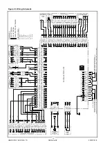
Neutral and Earth connections. See Figure 8.12 and
9.1 for details.
IMPORTANT :- READ THE WARNING NOTE
REGARDING EXTERNAL VOLTAGES.
11.2 Gas Installation
For design see
Section 5: GAS SUPPLY.
The whole of the gas installation including the meter
must be inspected and tested for soundness and
purged in accordance with the recommendations of
BS 6891 or IGE/UP/1 & IGE/UP/1A
as appropriate.
11.3 Water Circulation System
For design see
Section 8: WATER SYSTEM.
The system should be thoroughly flushed out with
cold water without the pump in position. Ensure all
the valves are open.
With the pump fitted the system should be filled and
air locks cleared. Vent the radiators and check for
leaks.
If the system is unvented the pressurisation unit
should not be utilised for the initial filling. This
should be carried out using a WRC approved double
check valve and temporary filling loop. In order to
comply with local Water Authority Regulations, this
loop must be disconnected when filling is complete.
Water treatment should not be fed through the
pressurisation unit unless permitted by the
manufacturer. Check the expansion vessel cushion
pressure as detailed by the manufacturer's
Installer's Guide.
11.4
Commissioning The Boiler
Only competent persons registered for working on
non domestic gas appliances should attempt the
following: Before attempting to commission any
boiler, ensure that personnel involved are aware of
what action is about to be taken and begin by
making the following checks:-
1)
Flueway passages to chimney are clear.
2)
Adequate ventilation as per
Section 7: AIR
SUPPLY
exists in the boiler house or compartment/
room.
3)
The system is fully charged with water, ready to
receive heat. All necessary valves are open and the
pump is circulating water.
4)
The pipework and valve arrangement is installed
to Hamworthy Heating recommendations in such a
way that water flow rates will be in accordance with
Figure 2.2.
5)
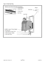
The gas supply pipework is clear of any loose
matter, tested for soundness and purged to
BS
6891 or IGE/UP/1 & IGE/UP/1A
as appropriate.
6)
The condensate discharge is connected to a
drain.
11.5.1 Boiler Checks Prior to Lighting
NOTE!
Refer to Figure 2.2. for Natural Gas
maximum inlet pressure for normal operation.
Information relating to propane firing can be found in
Appendix ‘A’.
1)
Ensure the gas supply is connected but turned to
the "OFF" position. Any unions or fittings are
correctly tightened and test points are closed.
2)
Ensure electricity is connected but switched
“OFF”. The plug/socket fan & gas valve connections
are correctly located and that the thermostat bulbs
are fully inserted into the pocket. Test the operation
of the temperature limiter by firmly pressing the
button (in controls fascia.), removing the clip and
bulb from the pocket and carefully applying a heat
source to the bulb. The reset button should operate.
If satisfactory, refit the bulb in the pocket and secure
with the clip.
3)
Check setting of both temperature limiter and
control thermostat. The temperature limiter must
not be set above 100°C maximum. Adjust if
required, by turning the setting screw in the direction
±. Set control thermostat to required temperature.
4)
With the fascia panel removed and hung on the
clips, access the terminal connections at the bottom
of the main PCB. Figure 9.1 shows the correct
location of incoming wires. Check for correct setting
of rotary switch ‘SW1’ on the control panel main
PCB – refer to Figure 8.12 for details. Remove the
wire link on connector ‘J4’ (black wire) on the PCB
and insert a multi-meter set to read DC µA..
5)
The Sherborne
boiler is fully modulating, with the
output dependant upon the control thermostat
demand, hence to achieve max output the system
must be cold.
24
Summary of Contents for Sherborne S65
Page 8: ...HAMWORTHY HEATING LTD SHERBORNE 500001103 E Figure 1 1 Boiler Installation Typical 2 ...
Page 29: ...HAMWORTHY HEATING LTD SHERBORNE 500001103 E Figure 10 6 Gas Pipe Fitting 23 ...
Page 45: ...HAMWORTHY HEATING LTD SHERBORNE 500001103 E NOTES 39 ...
Page 46: ...HAMWORTHY HEATING LTD SHERBORNE 500001103 E NOTES 40 ...
Page 47: ...Notes ...


