


HAMWORTHY HEATING LTD
SHERBORNE
500001103/E
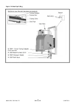
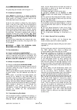
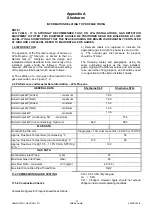
10.5 Condense Trap Connection
Select the condense trap kit from the Accessory
Pack. The condense trap is fitted to all boiler
models. Secure the trap to the sump casting using
the gasket and 2 M6 screws provided. Fit the 1/4”
BSP cap head plug. The trap is suitable for
connection to 22mm plastic waste pipe (not HHL
supply) with the waste pipe being routed through the
aperture in the wall frame adjacent to the gas
connection. A small amount of sealant must be used
on the waste pipe connection to the condense trap –
see Figure 10.5.
Figure 10.5 Condense Trap
10.6 Gas Connection
Assemble the gas isolating valve and union
assembly to the wall frame and connect the gas
supply to the Rc 3/4” connection on the isolating
valve - see Figure 10.6 / Page 23.
10.7 Fitting the Control Panel
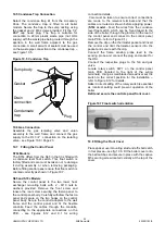
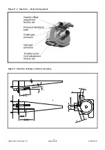
S70c Models
The S70c differs from the S65 in that it is fitted with
a condense level float switch. This float switch is
factory fitted and care must be taken not to damage
it during assembly or when removing packaging.
Before fitting control panel ensure that float switch is
oriented correctly as shown in Figure 10.7.
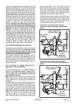
S65 and S70c Models
Secure the control panel to the two lower heat
exchanger mounting bolts with 2 - M10 nuts &
washers provided. Remove the front screw and
loosen the rear screw securing the fascia panel to
the control panel body. Carefully withdraw the fascia
panel and secure on the two hooks on the control
panel body. Secure the conduit adapters to the wall
frame and the control panel and fit the flexible
conduits. Feed the cables through the conduits,
connecting to the appropriate connections on the
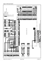
PCB. - see Figures 8.12 and 9.1 for wiring
Sump body
Gasket
Drain
connection
Condensate
trap
Plug
connection details.
Care must be taken to ensure correct connections
are made to the relevant terminals and that the
cables are routed as shown before applying power.
(
S70c model
- Feed the wires from the condense
level float switch, which can be found taped to the
side of the boiler, through the grommet in the rear of
the control panel and connect to the control panel
main PCB – refer to Figure 9.1.)
Remove the clip on the thermostat pocket and insert
the control and limit thermostat sensors into the
pocket and secure with the clip.
Connect the flame sensing probe lead to the
sensing probe and connect the plug and socket for
the HSI.
Connect the respective plugs to the fan and gas
valve.
Locate rotary switch ‘SW1’ on the control panel
main PCB (located to the right of the wiring
terminals). Using a small bladed screwdriver set the
switch to the correct position for the installation –
refer to Figure 8.12 for details.
N
ote:
Correct setting of the rotary switch is essential
as incorrect setting could prevent operation of the
boiler
Refit and secure the controls panel front cover.
10.8 Fitting the Front Cover
Place spacer over mounting stud and affix ball catch
in four places—see fig 10.6. Fit the boiler cover onto
the ball catches and secure in place with the captive
M5 securing screw located centrally at the top of the
cover.
Figure 10.7 Float switch orientation
22
Summary of Contents for Sherborne S65
Page 8: ...HAMWORTHY HEATING LTD SHERBORNE 500001103 E Figure 1 1 Boiler Installation Typical 2 ...
Page 29: ...HAMWORTHY HEATING LTD SHERBORNE 500001103 E Figure 10 6 Gas Pipe Fitting 23 ...
Page 45: ...HAMWORTHY HEATING LTD SHERBORNE 500001103 E NOTES 39 ...
Page 46: ...HAMWORTHY HEATING LTD SHERBORNE 500001103 E NOTES 40 ...
Page 47: ...Notes ...


