


32
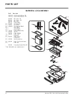
Hampton HG35-1 Direct Vent Freestanding Gas Stove
MAINTENANCE
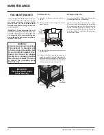
NORMAL OPERATING
SOUNDS OF
GAS APPLIANCES
It is possible that you will hear some sounds
from your gas appliance. This is perfectly normal
due to the fact that there are various gauges
and types of steel used within your appliance.
Listed below are some examples. All are
normal
operating sounds
and should not be considered
as defects in your appliance.
Blower:
Hampton gas appliances use high tech blowers
to push heated air farther into the room. It is not
unusual for the fan to make a "whirring" sound
when ON. This sound will increase or decrease
in volume depending on the speed setting of
your fan speed control.
Burner Tray:
The burner tray is positioned directly under the
burner tube(s) and logs and is made of a differ-
ent gauge material from the rest of the fi rebox
and body. Therefore, the varying thicknesses of
steel will expand and contract at slightly different
rates which can cause "ticking" and "cracking"
sounds. You should also be aware that as there
are temperature changes within the unit these
sounds will likely re-occur. Again, this is normal
for steel fi reboxes.
Gas Control Valve:
As the gas control valve turns ON and OFF, a
dull clicking sound may be audible, this is normal
operation of a gas regulator or valve.
Unit Body/Firebox:
Different types and thicknesses of steel will
expand and contract at different rates resulting
in some "cracking" and "ticking" sounds will be
heard throughout the cycling process.
CAUTION: ANY SAFETY SCREEN
OR GUARD REMOVED FOR SERV-
ICING AN APPLIANCE MUST BE
REPLACED PRIOR TO OPERAT-
ING THE APPLIANCE.
CLOTHING OR OTHER FLAM-
MABLE MATERIAL SHOULD NOT
BE PLACED ON OR NEAR THE
APPLIANCE.
DO NOT USE THIS APPLIANCE
IF ANY PART HAS BEEN UNDER
WATER. IMMEDIATELY CALL AN
AUTHORIZED SERVICE TECHNI
CIAN TO INSPECT THE APPLI-
ANCE AND TO REPLACE ANY
PART OF CONTROL SYSTEM AND
ANY GAS CONTROL WHICH HAS
BEEN UNDER WATER.
WARNING: CHILDREN AND
ADULTS SHOULD BE ALERTED
TO THE HAZARDS OF HIGH
SURFACE TEMPERATURE AND
SHOULD STAY AWAY TO AVOID
BURNS OR CLOTHING IGNITION.
YOUNG CHILDREN SHOULD BE
CAREFULLY SUPERVISED WHEN
THEY ARE IN THE SAME ROOM
AS THE APPLIANCE.
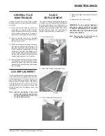
MAINTENANCE
INSTRUCTIONS
Any maintenance required accessing the
glass door of the unit must be performed
by an authorized service person.
1)
Always unplug the power cord before
cleaning. For relighting, refer to lighting
instructions. Keep the burner and control
compartment clean by brushing and vacu-
uming at least once a year. When cleaning
the logs, use a soft clean brush as the logs
are fragile and easily damaged.
2)
Clean glass (never when unit is hot), appli-
ance, louvres, and door with a damp cloth.
Never use an abrasive cleaner. The gold
louvres (and optional gold door) may be
scratched if abrasives are used to clean
them.
The heater is fi nished in a heat resistant
paint and should only be refi nished with
heat resistant paint (not with wall paint).
Regency uses StoveBright Paint - Metallic
Black #6309.
3)
Make a periodic check of burner for proper
position and condition. Visually check the
fl ame of the burner periodically, making sure
the fl ames are steady; not lifting or fl oating.
If there is a problem, call an authorized
service person.
4)
The appliance and fl ueing system must be
inspected before use, and at least annu-
ally, by an authorized fi eld service person,
to ensure that the fl ow of combustion and
ventilation air is not obstructed.
During the annual service call, the burners
should be removed from the burner tray
and cleaned. Replace the embers - do not
block the pilot or burner ports.
5)
Keep the area near the appliance clear and
free from combustible materials, gasoline
and other fl ammable vapours and liquids.
6)
Verify proper operation after servicing.


