


20
Hampton HG35-1 Direct Vent Freestanding Gas Stove
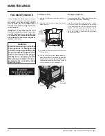
GAS PIPE
PRESSURE TESTING
The appliance must be isolated from the gas
supply piping system by closing its individual
manual shut-off valve during any pressure
testing of the gas supply piping system at test
pressures equal to or less than 1/2 psig. (3.45
kPa). Disconnect piping from valve at pressures
over 1/2 psig.
The manifold pressure is controlled by a regulator
built into the gas control, and should be checked
at the pressure test point.
Note: To properly check gas pressure, both
inlet and manifold pressures should
be checked using the valve pressure
ports on the valve.
1)
Make sure the valve is in the "OFF" posi-
tion.
2)
Loosen the "IN" and/or "OUT" pressure tap(s),
turning counterclockwise with a 1/8" wide fl at
screwdriver.
3)
Attach manometer to "IN" and/or "OUT"
pressure tap(s) using a 5/16" ID hose.
4)
Light the pilot and turn the valve to "ON"
position. Read manometer.
5)
The pressure check should be carried out
with the unit burning and the setting should
be within the limits specifi ed on the safety
label.
6)
When fi nished reading manometer, turn
off the gas valve, disconnect the hose and
tighten the screw (clockwise) with a 1/8" fl at
screwdriver.
Note: Screw should be snug,
but do not over tighten
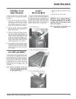
INSTALLATION
AERATION
ADJUSTMENT
The burner aeration is factory set but may need
adjusting due to either the local gas supply, air
supply or altitude.
Natural Gas
Fully Open
LPG
Fully Open
ULPG Fully
Open
Caution: Carbon will be produced if the air
shutter is closed too much.
Note: Any damage due to carboning result-
ing from improperly setting the aera-
tion controls is NOT covered under
warranty.
Note: Aeration Adjustment should only be
performed by an authorized Hampton
Installer at the time of installation or
service.
EV1
EV2
R.Q.
ADJ.
P.
OU
T
MD
4
3
2
1
Pin
11
8
9
10
1
2
3
4
6
7
5
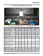
SIT 845 VALVE DESCRIPTION
1)
On-Off Solenoid Valve EV1
2)
On-Off Solenoid Valve EV2
3)
Inlet Pressure Test Point
4)
Outlet Pressure Test Point
5)
Connection for Pressure Regulator /
Combustion Chamber Compensation
6)
Pressure Regulator for Minimum and
Maximum Outlet Pressure
7)
Gas Outlet Pressure Electric Modulator
8)
Pilot
Outlet
9)
Main Gas Outlet
10)
Side Outlet
11)
Main Gas Inlet


