


26
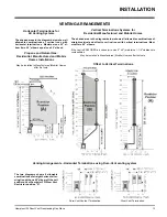
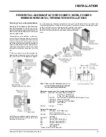
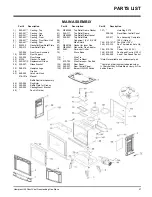
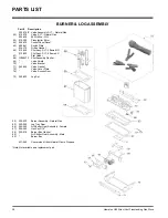
Hampton H25 Direct Vent Freestanding Gas Stove
INSTALLATION
THIS CONVERSION MUST
BE DONE BY A
QUALIFIED GAS
FITTER IF IN DOUBT DO
NOT DO THIS
CONVERSION !!
GAS PIPE
PRESSURE TESTING
The appliance must be isolated from the gas
supply piping system by closing its individual
manual shut-off valve during any pressure
testing of the gas supply piping system at test
pressures equal to or less than 1/2 psig. (3.45
kPa). Disconnect piping from valve at pressures
over 1/2 psig.
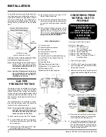
The manifold pressure is controlled by a regu-
lator built into the gas control, and should be
checked at the pressure test point.
Note: To properly check gas pressure,
both inlet and manifold pressures
should be checked using the valve
pressure ports on the valve.
1)
Make sure the valve is in the "OFF" position.
2)
Loosen the "IN" and/or "OUT" pressure tap(s),
turning counterclockwise with a 1/8" wide
flat screwdriver.
3)
Attach manometer to "IN" and/or "OUT" pres-
sure tap(s) using a 5/16" ID hose.
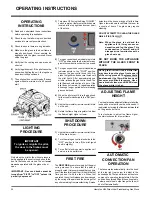
To adjust the aeration: use the allen key to turn
the turning gear which will adjust the air shutter.
Open the air shutter for a blue flame or close it
for a more yellow flame. This adjustment is
performed by a qualified installer. The factory
setting should be sufficient for most installa-
tions.
Clockwise to open,
counter-clockwise to close.
Caution: Carbon will be produced if the
air shutter is closed too much.
Note: Any damage due to carboning re-
sulting from improperly setting
the aeration controls is NOT cov-
ered under warranty.
Note: Aeration Adjustment should only
be performed by an authorized
Hampton Installer at the time of
installation or service.
4)
Light the pilot and turn the valve to "ON"
position. Read manometer.
5)
The pressure check should be carried out
with the unit burning and the setting should
be within the limits specified on the safety
label.
6)
When finished reading manometer, turn off
the gas valve, disconnect the hose and
tighten the screw (clockwise) with a 1/8"
flat screwdriver.
Note: Screw should be
snug, but do not over tighten
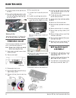
Valve Description
1)
Gas cock knob
2)
Manual high/low adjustment
3)
Pilot Adjustment
4)
Thermocouple Connection
5)
Main Operator
6)
Outlet Pressure Tap (Manifold Pressure)
7)
Inlet Pressure Tap (Supply Pressure)
8)
Pilot Outlet
9)
Main Gas Outlet
10)
Flange Securing Screw Holes
11)
Alternative TC Connection Point
12)
Thermoelectric Unit
13)
Additional Valve Mounting Hole
CONVERSION FROM
NATURAL GAS T O
PROPANE
Conversion Kit #431-969 Contains:
Qty. Part #
Description
1 910-018
SIT Conversion Kit-
50% Turndown LP
1 910-037
LP Injector (Pilot Orifice)
1 904-163
Burner Orifice #54
1 908-528
Red "PROPANE" label
1 908-255
Label "Converted to Propane"
1
Instruction Sheet
1) Shut off the gas supply.
2) Lift off the Cast Top and remove the glass
front (see page 35) and carefully remove
the logs and lava rock.
3) Remove burner by removing the 2 screws
on each side and then lifting the burner tray
out.
Pilot
assembly is
now accessi-
ble for steps
4) to 9).
Note: Use a magnetic type screwdriver if pos-
sible.
4) Remove and discard the 3 pressure regu-
lator mounting screws (A), pressure reg-
ulator tower (B) and diaphragm (C).
5) Insure that the rubber gasket (D) is properly
positioned and install the new HI/LO pres-
sure regulator assembly to the valve using
the new screws (E) supplied with the kit.
Tighten screws securely.
Screws


